Data Transmission and Reception
11-23
Multichannel Buffered Serial Ports
11.3.4 Frame and Clock Configuration
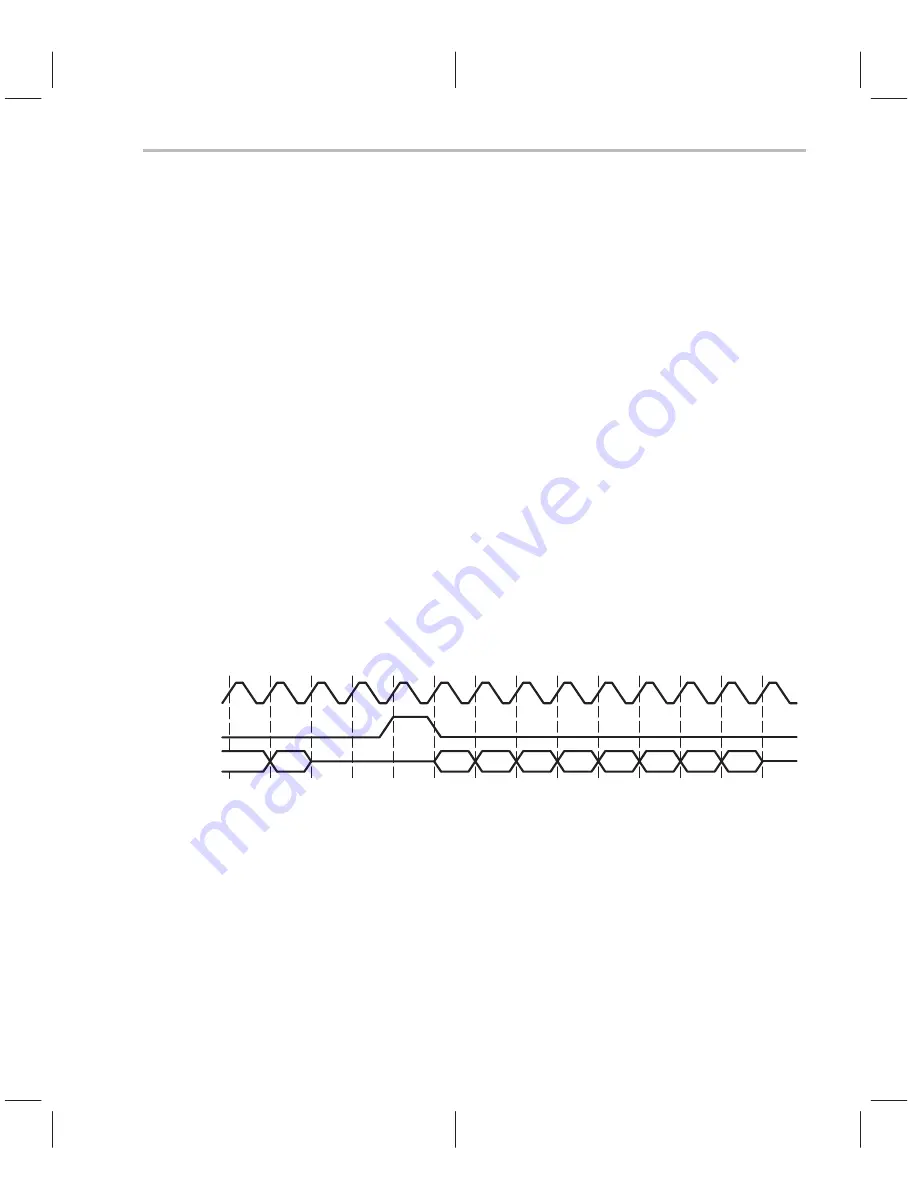
Figure 11–6 shows typical operation of the McBSP clock and frame sync sig-
nals. Serial clocks CLKR and CLKX define the boundaries between bits for re-
ceive and transmit, respectively. Similarly, frame sync signals FSR and FSX
define the beginning of an element transfer. The McBSP allows configuration
of the following parameters for data and frame synchronization:
-
Polarities of FSR, FSX, CLKX, and CLKR
-
A choice of single- or dual-phase frames
-
For each phase, the number of elements per frame
-
For each phase, the number of bits per element
-
Whether subsequent frame synchronization restarts the serial data
stream or is ignored
-
The data delay from frame synchronization to first data bit which can be
0-, 1-, or 2-bit delays
-
Right or left justification as well as sign extension or zero filling for receive
data
The configuration can be independent for receive and transmit.
Figure 11–6.Frame and Clock Operation
D(R/X)
FS(R/X)
CLK(R/X)
B3
B2
B1
B0
B5
B4
B6
B7
A0
A1
ÁÁ
ÁÁ
ÁÁ
ÁÁ
Á
Á
11.3.4.1 Frame and Clock Operation
Receive and transmit frame sync pulses can either be generated internally by
the sample rate generator (see section 11.5.1) or be driven by an external in-
put. The source of frame sync is selected by programming the mode bit,
FS(R/X)M, in the PCR. FSR is also affected by the GSYNC bit in the SRGR
(see section 11.5.3.2 for details). Similarly, receive and transmit clocks can be
selected to be inputs or outputs by programming the mode bit, CLK(R/X)M, in
the PCR.
When FSR and FSX are inputs (FSXM = FSRM = 0), the McBSP detects them
on the internal falling edge of clock, CLKR_int and CLKX_int, respectively (see


