Direct Memory Access Using the HOLD Operation
4-27
Memory and I/O Spaces
4.7
Direct Memory Access Using the HOLD Operation
The ’C2xx HOLD operation allows direct-memory access to external program,
data, and I/O spaces. The process is controlled by two signals:
-
HOLD. An external device can drive the HOLD/INT1 pin low to request
control over the external buses. If the HOLD/INT1 interrupt line is enabled,
this triggers an interrupt.
-
HOLDA. In response to a HOLD interrupt, software logic can cause the
processor to issue a HOLD acknowledge (HOLDA pin low), to indicate that
it is relinquishing control of its external lines. Upon HOLDA, the external
address signals (A15–A0), data signals (D15–D0), and memory-control
signals (PS, DS, BR, IS, STRB, R/W, RD, WE) are placed in high imped-
ance.
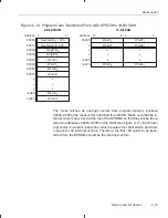
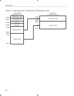
Following a negative edge on the HOLD/INT1 pin, if interrupt line HOLD/INT1
is enabled, the CPU branches to address 0002h (this branch could also be ac-
complished with an INTR 1 instruction). Here the CPU fetches the interrupt
vector and follows it to the interrupt service routine. If you wish to use this rou-
tine for HOLD operations and also for the interrupt INT1, the tasks carried out
by this routine will depend on the value of the MODE bit:
-
MODE = 1. When the CPU detects a negative edge on HOLD/INT1, it
finishes executing the current instruction (or repeat operation) and then
forces program control to the interrupt service routine. The interrupt ser-
vice routine, after successfully testing for MODE = 1, performs the tasks
for INT1.
-
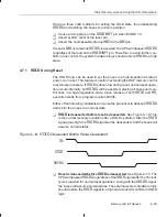
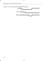
MODE = 0. Interrupt line INT1 is both negative- and positive-edge sensi-
tive. When the CPU detects the negative edge, it finishes executing the
current instruction (or repeat operation) and then forces program control
to the interrupt service routine. This routine, after successfully testing for
MODE = 0, executes an IDLE instruction. Upon IDLE, HOLDA is asserted
and the external lines are placed in high impedance. Only after detecting
a rising edge on the HOLD/INT1 pin, the CPU exits the IDLE state,
deasserts HOLDA, and returns the external lines to their normal states.
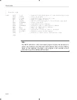
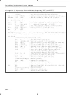
Example 4–1 shows an interrupt service routine that tests the MODE bit and
acts accordingly. Note that the IDLE instruction should be placed inside the in-
terrupt service routine to issue HOLDA. Also note that the interrupt program
code disables all maskable interrupts except HOLD/INT1 to allow safe recov-
ery of HOLDA and the buses. Any other sequence of CPU code will cause un-
desirable bus control and is not recommended. (Interrupt operation is ex-
plained in detail in Section 5.6 on page 5-15.)


