Emulation Timing Calculations
E-7
Design Considerations for Using XDS510 Emulator
E.5 Emulation Timing Calculations
Example E–1 and Example E–2 help you calculate emulation timings in your
system. For actual target timing parameters, see the appropriate data sheet
for the device you are emulating.
The examples use the following assumptions:
t
su(TTMS)
Setup time, target TMS or TDI to TCK
high
10 ns
t
d(TTDO)
Delay time, target TDO from TCK low
15 ns
t
d(bufmax)
Delay time, target buffer maximum
10 ns
t
d(bufmin)
Delay time, target buffer minimum
1 ns
t
bufskew
Skew time, target buffer between two de-
vices in the same package:
[t
d(bufmax)
– t
d(bufmin)
]
×
0.15
1.35 ns
t
TCKfactor
Duty cycle, assume a 40/60% duty cycle
clock
0.4
(40%)
Also, the examples use the following values from Table E–2 on page E-6:
t
d(TMSmax)
Delay time, emulator TMS or TDI from
TCK_RET low, maximum
20 ns
t
su(TDOmin)
Setup time, TDO to emulator TCK_RET
high, minimum
3 ns
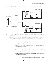
There are two key timing paths to consider in the emulation design:
-
The TCK_RET-to-TMS or TDI path, called t
pd(TCK_RET-TMS/TDI)
(propaga-
tion delay time)
-
The TCK_RET-to-TDO path, called t
pd(TCK_RET-TDO)
In the examples, the worst-case path delay is calculated to determine the
maximum system test clock frequency.


