Load Status Register
LST
7-87
Assembly Language Instructions
Syntax
LST #
m, dma Direct
addressing
LST
#
m,
ind [, ARn]
Indirect addressing
Operands
dma:
7 LSBs of the data-memory address
n:
Value from 0 to 7 designating the next auxiliary register
m:
Select one of the following:
0
Indicates that ST0 will be loaded
1
Indicates that ST1 will be loaded
ind:
Select one of the following seven options:
* *+ *– *0+ *0– *BR0+ *BR0–
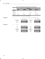
LST #0,
dma
15
14
13
12
11
10
9
8
7
6
5
4
3
2
1
0
0
0
0
0
1
1
1
0
0
dma
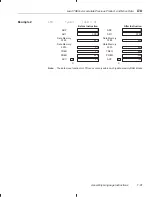
LST #0,
ind [, ARn]
15
14
13
12
11
10
9
8
7
6
5
4
3
2
1
0
0
0
0
0
1
1
1
0
1
ARU
N
NAR
Note:
ARU, N, and NAR are defined in Section 6.3,
Indirect Addressing Mode (page 6-9).
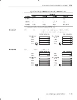
LST #1,
dma
15
14
13
12
11
10
9
8
7
6
5
4
3
2
1
0
0
0
0
0
1
1
1
1
0
dma
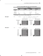
LST #1,
ind [, ARn]
15
14
13
12
11
10
9
8
7
6
5
4
3
2
1
0
0
0
0
0
1
1
1
1
1
ARU
N
NAR
Note:
ARU, N, and NAR are defined in Section 6.3,
Indirect Addressing Mode (page 6-9).
Execution
Increment PC, then ...
(data-memory address)
→
status register STm
For details about the differences between an LST #0 operation and an LST #1
operation, see Figure 7–3, Figure 7–4, and the description category below.
Figure 7–3. LST #0 Operation
15
14
13
12
11
10
9
8
7
6
5
4
3
2
1
0
Data
↓
↓
↓
↓
↓
↓
↓
↓
↓
↓
↓
↓
↓
↓
15
14
13
12
11
10
9
8
7
6
5
4
3
2
1
0
ST0
ARP
OV
OVM
1
INTM
DP
Opcode


