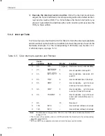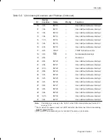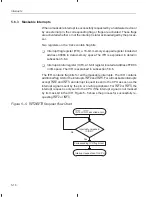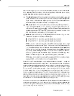
Interrupts
5-24
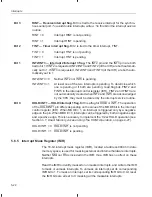
Bit 0
HOLD/INT1 — HOLD/Interrupt 1 mask. This bit masks or unmasks interrupts re-
quested at the HOLD/INT1 pin.
HOLD/INT1 = 0 HOLD/INT1 is masked.
HOLD/INT1 = 1 HOLD/INT1 is unmasked.
5.6.6
Interrupt Control Register (ICR)
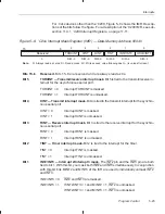
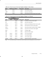
The 16-bit interrupt control register (ICR), located at address FFECh in I/O
space, controls the function of the HOLD/INT1 pin and individually controls the
interrupts INT2 and INT3.
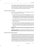
Controlling the HOLD/INT1 pin
This pin can be used for triggering the interrupt INT1 and for sending a HOLD
signal to the CPU. Accordingly, the MODE bit provides two possible modes for
the HOLD/INT1 pin. When MODE = 1, the pin is negative-edge sensitive and,
thus, is set appropriately for initiating a standard interrupt (INT1). When
MODE = 0, the pin is both negative- and positive-edge sensitive, which is nec-
essary for implementing the logic for the HOLD operation (see Section 4.7,
Di-
rect Memory Access Using The HOLD Operation, on page 4-27). Regardless
of the value of MODE, the pin is connected to the same interrupt logic, which
initiates only one interrupt service routine. (HOLD/INT1 is mapped to interrupt
vector location 0002h in program memory.) To differentiate the two uses of the
pin, the interrupt service routine must test the value of the MODE bit.
Controlling INT2 and INT3
Each of these interrupts has its own pin. However, they share:
-
A single flag bit (INT2/INT3) in the interrupt flag register (IFR).
-
A single mask bit in the interrupt mask register (IMR).
-
A single interrupt service routine. (INT2 and INT3 are mapped to interrupt
vector location 0004h in program memory.)
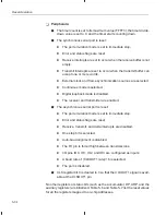
To allow you to use INT2 and INT3 individually, the ICR provides two mask bits
(MINT2 and MINT3) and two flag bits (FINT2 and FINT3).
When interrupts are requested on the pins INT2 and INT3, MINT2 and MINT3
determine whether the flag bits FINT2, FINT3, and INT2/INT3 are set. To mask
INT2 (prevent the setting of flags FINT2 and INT2/INT3), write a 0 to MINT2;


