Troubleshooting
9-28
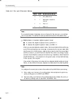
Table 9–6. Run and Emulation Modes
ÁÁÁ
ÁÁÁ
FREE
ÁÁÁ
ÁÁÁ
SOFT
ÁÁÁÁÁÁÁÁ
ÁÁÁÁÁÁÁÁ
Run/Emulation Mode
ÁÁÁ
ÁÁÁ
0
ÁÁÁ
ÁÁÁ
0
ÁÁÁÁÁÁÁÁ
ÁÁÁÁÁÁÁÁ
Immediate stop
ÁÁÁ
Á
Á
Á
ÁÁÁ
0
ÁÁÁ
Á
Á
Á
ÁÁÁ
1
ÁÁÁÁÁÁÁÁ
Á
ÁÁÁÁÁÁ
Á
ÁÁÁÁÁÁÁÁ
Stop after completion
of word
ÁÁÁ
ÁÁÁ
1
ÁÁÁ
ÁÁÁ
0
ÁÁÁÁÁÁÁÁ
ÁÁÁÁÁÁÁÁ
Free run
ÁÁÁ
Á
Á
Á
ÁÁÁ
1
ÁÁÁ
Á
Á
Á
ÁÁÁ
1
ÁÁÁÁÁÁÁÁ
Á
ÁÁÁÁÁÁ
Á
ÁÁÁÁÁÁÁÁ
Free run
Note:
If an option besides immediate stop is chosen for the receiver, an overflow
error is possible. The default mode (selected at reset) is
immediate stop.
-
DLB enables or disables digital loopback mode:
J
To enable the digital loopback mode, set DLB = 1.
J
To disable the digital loopback mode, set DLB = 0.
When you enable digital loopback mode, the transmit data (DX) and frame
sync (FSX) signals become internally connected to the receive data (DR)
and frame sync (FSR) signals. After writing code for both the transmitter
and the receiver, you can then test whether the code is working properly
and also check that the serial port is functioning. In addition, if both the DLB
and MCM bits are 1, the transmit clock signal is also connected internally
to the receive clock signal.
The serial port operates normally when you disable digital loopback mode;
that is, no transmit and receive signals are internally connected together.
Note:
To configure the serial port, a total of two writes to the SSPCR are necessary:
1) First, write your choices to the configuration bits and place the port in re-
set by writing zeros to XRST and RRST.
2) Second, write your choices to the configuration bits and take the port out
of reset by writing ones to the XRST and RRST bits.


