background image

© 2015 UTC RETAIL  


11933016 Rev A 


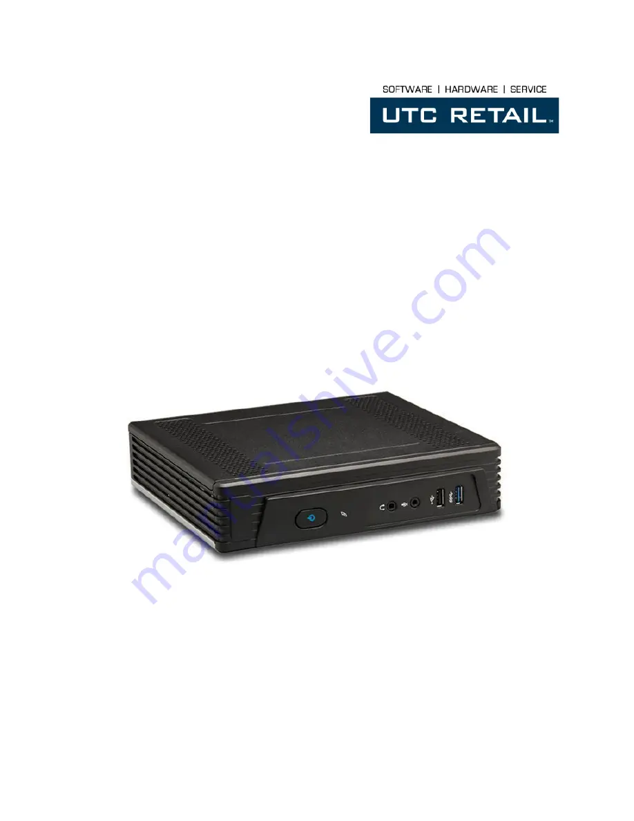
1170 POS SYSTEM 

1170 USER GUIDE 

Thank you for selecting UTC RETAIL’s innovative Model 1170 Point of Sale solution!  

This guide is designed to acquaint you with the features and functionality of the 1170 Point of Sale System. 


Содержание 1170

Страница 1: ...Rev A 1170 POS SYSTEM 1170 USER GUIDE Thank you for selecting UTC RETAIL s innovative Model 1170 Point of Sale solution This guide is designed to acquaint you with the features and functionality of the 1170 Point of Sale System ...

Страница 2: ... been tested and found to comply with the limits for a Class A digital device pursuant to Part 15 of the FCC Rules These limits are designed to provide reasonable protection against harmful interference when the equipment is operated in a commercial environment This equipment generates uses and can radiate radio frequency energy and if not installed and used in accordance with the instruction manu...

Страница 3: ...170 POS System Specifications 6 1170 Input Output Ports 7 Front I O Panel 7 Power Switch 7 Hard Drive LED 7 Audio Output 7 Microphone 7 USB 2 0 7 USB 3 0 8 Rear I O Panel 8 Kensington Lock 8 System Power 8 PS 2 8 Parallel Port 8 Video 8 Serial Ports 9 Network 9 USB 9 Antenna 9 Installation 9 Configuration and Maintenance 9 BIOS and Boot Menu 9 Top Cover Removal 9 ...

Страница 4: ...RETAIL All rights reserved Hard Drive Access 10 Serial Port 10 mSATA and mini PCIe 10 CMOS BIOS Clear Deep Sleep 11 Supported Peripheral Options Details 12 Power Requirements 12 Expansion Options 12 System Installation Guide 12 ...

Страница 5: ...uration you have purchased the following optional items may also be installed in the 1170 POS WLAN 802 11 mini PCIe PERIPHERAL SUPPORT The 1170 POS System accepts a standard PC keyboard and standard mouse with a PS 2 or USB interface UTC RETAIL P N 10718020 contains both a USB keyboard and USB mouse The 1170 POS System was designed to coordinate with the UTC RETAIL PD1200 Pole Display option The 1...

Страница 6: ... 2 keyboard and mouse RS 232 Ports 2 DB9 USB Interface Ports 1 USB 3 0 5 USB 2 0 Network Ports 2 10 100 1000 Realtek PCI GBE Family LAN Parallel Port 1 DB25 Wireless LAN optional 802 11 a b g n WLAN and mSATA mutually exclusive Customer Displays optional 2 line x 20 character PD1200 VFD free standing Keyboard options Standard PC with USB or PS 2 interface Cash Drawer Optional Dimensions W x D x H ...

Страница 7: ...he switch press and hold it for 4 seconds HARD DRIVE LED The LED 2 will blink when the operating system is accessing the hard drive AUDIO OUTPUT The Line Out jack 3 accepts a standard 3 5 audio plug and will send audio to a set of headphones or standard PC speakers The speakers must use an external power supply for power Volume control is perform from the speakers from Windows volume control or th...

Страница 8: ...SB 2 0 15 USB 2 0 16 WLAN dipole KENSINGTON LOCK The Kensington Security Slot 1 is used for attaching a lock and cable apparatus SYSTEM POWER To prevent system problems and or electronic damage only use the 1170 POS AC adapter obtained from the product box or a replacement from UTC RETAIL The unit s warranty is voided if incorrect power is applied to it Mate the adapter s barrel plug with the powe...

Страница 9: ...ng motherboard terminal block jumpers NETWORK The two LAN jacks 10 13 accept standard RJ 45 plugs and are used to interface the 1170 with your network USB The 4 USB ports 11 12 14 and 15 are USB 2 0 ports and may be used to interface with standard PC accessories and USB interface Point Of Service devices ANTENNA The antenna 16 lead internal attaches to the optional internal WLAN accessory and is u...

Страница 10: ...he tray When installing the tray ensure the tab on the left rear engages in the slot on the chassis frame SERIAL PORT COM Port 2 COM2 Terminal Blocks and Jumper Settings move the jumpers to customize COM2 port configuration PIN COM2 Default COM2 User defined 1 SP1 DCD 1 2 DCD 1 2 5V 3 4 2 SP2 RXD 1 2 RXD 1 2 TXD 3 4 RXD TTL 5 6 TXD TTL 7 8 3 SP3 TXD 1 2 TXD 1 2 RXD 3 4 TXD TTL 5 6 RXD TTL 7 8 4 SP...

Страница 11: ...L All rights reserved CMOS Clear J7 Deep Sleep J26 Normal 1 2 Default Normal 1 X Default CMOS clear 2 3 Deep Sleep enable 1 2 Function J4 J6 mSATA 3 5 4 6 3 5 4 6 mini PCIe 1 3 2 4 1 3 2 4 Table 2 J4 and J6 CMOS BIOS CLEAR DEEP SLEEP ...

Страница 12: ... support post Remove the HDD see Hard Drive Access Remove the M2 screw from the WLAN support post Attach the 2 antenna leads from the 1170 POS antennas to the card s antenna jacks Set the card into its slot press it down against the post and secure it with the M2 screw Ensure J4 and J6 are set for mini PCIe as seen in Table 2 Reinstall the HDD 3 mSATA a mSATA storage card may be used in place of o...

Отзывы: