


Options
159
13.4
I/O Board
The I/O option board 2.0 provides three extra relay out-
puts and three extra digital inputs. The I/O Board works
in combination with the Pump/Fan Control, but can
also be used as a separate option. This option is
described in a separate manual.
13.5
Output coils
Output coils, which are supplied separately, are recom-
mended for lengths of screened motor cable longer
than 100 m. Because of the fast switching of the motor
voltage and the capacitance of the motor cable both
line to line and line to earth screen, large switching cur-
rents can be generated with long lengths of motor
cable. Output coils prevent the VSD from tripping and
should be installed as closely as possible to the VSD.
13.6
Serial communication
and fieldbus
For communication with the VSD there are several
option boards for communication. There are different
options for Fieldbus communication and one serial
communication option with RS232 or RS485 interface
which has galvanic isolation.
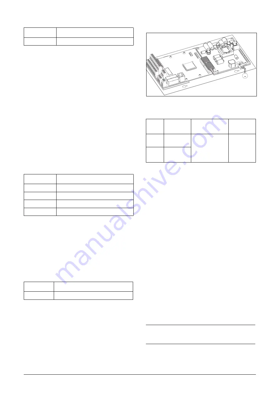
13.7
Standby supply board
option
The standby supply board option provides the possibil-
ity of keeping the communication system up and run-
ning without having the 3-phase mains connected. One
advantage is that the system can be set up without
mains power. The option will also give backup for com-
munication failure if main power is lost.
The standby supply board option is supplied with exter-
nal
±10% 24 V
DC
or 24 V
AC,
protected by a 2 A slow acting
fuse, from a double isolated transformer. The terminals
X1:1 and X1:2 are voltage polarity independent.
Fig. 123 Connection of standby supply option
13.8
Safe Stop option
To realize a Safe Stop configuration in accordance with
EN954-1 Category 3, the following three parts need to
be attended to:
1. Inhibit trigger signals with safety relay K1 (via Safe
Stop option board).
2. Enable input and control of VSD (via normal I/O con-
trol signals of VSD).
3. Power conductor stage (checking status and feed-
back of driver circuits and IGBT’s).
To enable the VSD to operate and run the motor, the fol-
lowing signals should be active:
• "Inhibit" input, terminals 1 (DC+) and 2 (DC-) on the
Safe Stop option board should be made active by
connecting 24 V
DC
to secure the supply voltage for
the driver circuits of the power conductors via safety
relay K1. See also Fig. 126.
• High signal on the digital input, e.g. terminal 9 in
Fig. 126, which is set to "Enable". For setting the dig-
ital input please refer to section 11.5.2, page 123.
These two signals need to be combined and used to
enable the output of the VSD and make it possible to
activate a Safe Stop condition.
Order number
Description
01-3876-01
I/O option board 2.0
Order number
Description
01-3876-04
RS232/485
01-3876-05
Profibus DP
01-3876-06
DeviceNet
01-3876-09
Modbus/TCP, Ethernet
Order number
Description
01-3954-00
Standby power supply kit for after mounting
Table 36
X1
terminal
Name
Function
Specification
1
Ext. supply 1
External, VSD main
power independ-
ent, supply voltage
for control and com-
munication circuits
24 V
DC
or 24
V
AC
±10%
Double iso-
lated
2
Ext. supply 2
NOTE: The "Safe Stop" condition according to EN 954-1
Category 3 can only be realized by de-activating both the
"Inhibit" and "Enable" inputs.
~
Must be
double
isolated
X1:1 Left terminal
X1:2 Right terminal
X1
Содержание F33 Series
Страница 1: ...TECO F33 Variable Speed Drive Instruction manual English Software version 4 2X...
Страница 3: ......
Страница 33: ...30 Getting Started...
Страница 51: ...48 Main Features...
Страница 53: ...50 EMC and Machine Directive...
Страница 59: ...56 Operation via the Control Panel...
Страница 65: ...62 Serial communication...
Страница 159: ...156 Troubleshooting Diagnoses and Maintenance...
Страница 165: ...162 Options...
Страница 179: ...176 Technical Data...
Страница 187: ...184 Menu List...