


4A-1 Brake Control System and Diagnosis:
Brake
Brake Control System and Diagnosis
Schematic and Routing Diagram
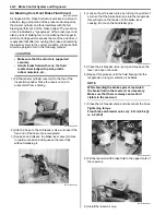
Front Brake Hose Routing Diagram
B931H24102001
1
“B”
2
“C”
3
4
5
5
7
4
(a)
8
9
4
(a)
8
9
10
11
11
12
(a)
8
11
“E”
6
“F”
(b)
“D”
(b)
“A”
“D”
“D”
I931H1410043-05
1. Master cylinder
11. Suspension upper arm
2. Front brake hose No. 1
12. Radiator hose
3. Front brake pipe
“A”: UP mark.
4. Front brake hose No. 2
“B”: After the brake hose union has contacted the reservoir bottom.
5. Front brake caliper
“C”: Pass the brake hose behind the throttle cable.
6. Frame
“D”: Fix the brake hose to the it guide firmly.
7. Steering shaft
“E”: Pass the brake hose No. 2 between the radiator lower hose and frame.
8. Union bolt
“F”: Pass the brake hose inside of the suspension arm.
9. Stopper
: After the brake hose union has contacted the stopper,
tighten the union bolt.
: 23 N
⋅
m (2.3 kgf-m, 16.5 lbf-ft)
10. Stopper
: After the brake hose clamp has contacted the
suspension upper arm, tighten the stopper bolt.
: 16 N
⋅
m (1.6 kgf-m, 11.5 lbf-ft)
Содержание 2009 LT-A500XP
Страница 2: ......
Страница 4: ......
Страница 14: ...00 9 Precautions ...
Страница 224: ...1E 3 Engine Lubrication System EXHAUST SIDE INTAKE SIDE I931H1150003 02 ...
Страница 304: ...1K 4 Exhaust System ...
Страница 346: ...2D 5 Wheels and Tires ...
Страница 438: ...3D 26 Propeller Shafts ...
Страница 482: ...4D 6 Parking Brake ...
Страница 512: ...5A 28 Automatic Transmission ...
Страница 582: ...9 ii Table of Contents Specifications 9E 7 Tightening Torque Specifications 9E 7 Special Tools and Equipment 9E 7 ...
Страница 624: ...Prepared by December 2008 Part No 99500 44080 03E Printed in U S A 624 ...