


1A-41 Engine General Information and Diagnosis:
C15 (Use of mode select switch)
Step
Action
Yes
No
1
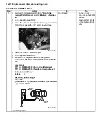
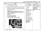
1) Remove the right side cover. Refer to
“Front Side
Exterior Parts Removal and Installation: in Section
9D”
.
2) Turn the ignition switch OFF.
3) Check the ECT sensor coupler for loose or poor
contacts.
If OK, then measure the ECT sensor voltage at the wire
side coupler.
4) Disconnect the coupler and turn the ignition switch ON.
5) Measure the voltage between the B/Bl wire terminal and
ground.
If OK, then measure the input voltage between B/Bl wire
terminal and B/Br wire terminal.
Special tool
(A): 09900–25008 (Multi-circuit tester set)
Tester knob indication
Voltage (
)
ECT sensor voltage
4.5 – 5.5 V
((+) terminal: B/Bl – (–) terminal: Ground, (+)
terminal: B/Bl – (–) terminal: B/Br)
Is the voltage OK?
Go to Step 2.
• Loose or poor
contacts on the ECM
coupler.
• Open or short circuit
in the B/Bl or B/Br
wire.
I931H1110035-01
(A)
I718H1110048-03
Содержание 2009 LT-A500XP
Страница 2: ......
Страница 4: ......
Страница 14: ...00 9 Precautions ...
Страница 224: ...1E 3 Engine Lubrication System EXHAUST SIDE INTAKE SIDE I931H1150003 02 ...
Страница 304: ...1K 4 Exhaust System ...
Страница 346: ...2D 5 Wheels and Tires ...
Страница 438: ...3D 26 Propeller Shafts ...
Страница 482: ...4D 6 Parking Brake ...
Страница 512: ...5A 28 Automatic Transmission ...
Страница 582: ...9 ii Table of Contents Specifications 9E 7 Tightening Torque Specifications 9E 7 Special Tools and Equipment 9E 7 ...
Страница 624: ...Prepared by December 2008 Part No 99500 44080 03E Printed in U S A 624 ...