Drive Chain / Drive Train / Drive Shaft: 3A-2
Front Drive Shaft Assembly Removal and
Installation
B931H23106002
Removal
1) Drain the front differential gear oil. Refer to
“Front
Differential Gear Oil Inspection: in Section 0B”
.
2) Remove the front wheel. Refer to
“Front / Rear
Wheel Removal and Installation: in Section 2D”
.
3) Remove the steering knuckle. Refer to
“Front
Wheel Hub / Steering Knuckle Removal and
Installation: in Section 2B”
.
4) Hold the inboard joint (1) of the front drive shaft and
tug the drive shaft horizontally.
NOTE
If it is difficult to remove the front drive shaft
from the front differential gear case, use the
suitable tool.
Installation
Install the front drive shaft assembly in the reverse order
of removal. Pay attention to the following points:
• Install a new circlip into the groove of front differential
gear spline.
CAUTION
!
The removed circlip must be replaced with a
new one.
• Apply grease to the spline of the front drive shafts.
: Grease 99000–25010 (SUZUKI SUPER
GREASE A or equivalent)
• Apply grease to the lip of the oil seal and install the
front drive shafts to the front differential gear case.
: Grease 99000–25160 (Water resistance
grease or equivalent)
CAUTION
!
Be careful not to damage the front differential
gear case oil seals.
NOTE
After installing both drive shafts, make sure
the stopper rings are seated properly by
pulling both inboard joints lightly.
• Install the steering knuckle. Refer to
“Front Wheel
Hub / Steering Knuckle Removal and Installation:
in Section 2B”
.
• Install the front wheel. Refer to
“Front / Rear Wheel
Removal and Installation: in Section 2D”
.
• Pour the front differential gear oil. Refer to
“Front
Differential Gear Oil Inspection: in Section 0B”
.
Front Drive Shaft Disassembly and Assembly
B931H23106003
Refer to “Front Drive Shaft Assembly Removal and
Installation (Page 3A-2)”.
Disassembly
CAUTION
!
Do not disassemble the wheel side joint. If
any damages are found, replace it with a new
one.
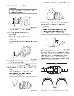
1) Remove the boot band of the differential side joint.
1
I931H1310001-02
I931H1310002-03
I931H1310003-03
Содержание 2009 LT-A500XP
Страница 2: ......
Страница 4: ......
Страница 14: ...00 9 Precautions ...
Страница 224: ...1E 3 Engine Lubrication System EXHAUST SIDE INTAKE SIDE I931H1150003 02 ...
Страница 304: ...1K 4 Exhaust System ...
Страница 346: ...2D 5 Wheels and Tires ...
Страница 438: ...3D 26 Propeller Shafts ...
Страница 482: ...4D 6 Parking Brake ...
Страница 512: ...5A 28 Automatic Transmission ...
Страница 582: ...9 ii Table of Contents Specifications 9E 7 Tightening Torque Specifications 9E 7 Special Tools and Equipment 9E 7 ...
Страница 624: ...Prepared by December 2008 Part No 99500 44080 03E Printed in U S A 624 ...


