


RM0008
Universal synchronous asynchronous receiver transmitter (USART)
Doc ID 13902 Rev 12
789/1096
27.3.14 Hardware
flow
control
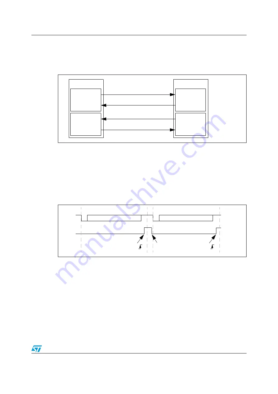
It is possible to control the serial data flow between 2 devices by using the nCTS input and
the nRTS output. The
shows how to connect 2 devices in this mode:
Figure 297. Hardware flow control between two USARTs
RTS and CTS flow control can be enabled independently by writing respectively RTSE and
CTSE bits to 1 (in the USART_CR3 register).
RTS flow control
If the RTS flow control is enabled (RTSE=1), then nRTS is asserted (tied low) as long as the
USART receiver is ready to receive new data. When the receive register is full, nRTS is
deasserted, indicating that the transmission is expected to stop at the end of the current
frame.
shows an example of communication with RTS flow control enabled.
Figure 298. RTS flow control
CTS flow control
If the CTS flow control is enabled (CTSE=1), then the transmitter checks the nCTS input
before transmitting the next frame. If nCTS is asserted (tied low), then the next data is
transmitted (assuming that a data is to be transmitted, in other words, if TXE=0), else the
transmission does not occur. When nCTS is deasserted during a transmission, the current
transmission is completed before the transmitter stops.
When CTSE=1, the CTSIF status bit is automatically set by hardware as soon as the nCTS
input toggles. It indicates when the receiver becomes ready or not ready for communication.
An interrupt is generated if the CTSIE bit in the USART_CR3 register is set. The figure
below shows an example of communication with CTS flow control enabled.
USART 1
RX circuit
TX circuit
USART 2
TX circuit
RX circuit
RX
TX
TX
RX
nCTS
nRTS
nRTS
nCTS
Start
Bit
Stop
Bit
Data 1
IdleStart
Bit
Stop
Bit
Data 2
RX
nRTS
RXNE
Data 1 read
RXNE
Data 2 can now be transmitted