9
02.98
1-136
Siemens AG 1998 All Rights reserved 6SN1197–0AA00 02.98 Edition
SIMODRIVE 611 (PJ)
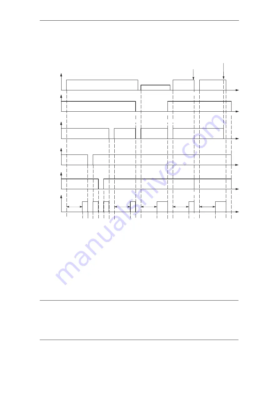
Timing diagram for ready signal in the NE module
Shutdown using the main switch, external line
contactor or another switching element.
Load supply
available
E
Supply voltage
Supply failure
Supply voltage
Setting–up voltage
Supply voltage
C
B
C
C
B
F
D
D
D
T. 112
T. 48
T. 64
T. 63
Ready
T. 72...74
A The ready relay can only pull–in, if charging has been completed and the internal line contactor
has pulled–in.
C When changing–over from setting–up operation, terminal 112 de–energized, in normal operation, terminal 112
energized, terminal 48 must also be de–energized either earlier, or at the same time. After the int. line contactor has
dropped–out, the line voltage can be re–connected. Line supply volt., refer to p. 1-62 ~ 1-70 (Technical Data,
NE module).
D The I/R module is internally inhibited when the line supply fails. This means that the infeed/regenerative
feedback module can no longer regulate the DC link voltage, and regenerative power can no longer be fed
back into the supply. The drives are not inhibited. However, the ready relay drops–out, after the supply failure
identification time, t
N OFF
, approx. 30 ms.
A
A
A
A
A
Caution!
E When shutting down the load supply using a main switch or an external line contactor, or using any other switching
elements, it must be ensured, that terminal 48 on the NE module is de–energized at least 10 ms prior to this
switching operation. This can be achieved, e. g. using a main switch with leading contact or interlocking circuits for
the external line contactor or switching element.
F If the DC link voltage falls below 290 V, then all of the modules are inhibited (the drives coast down) and
the internal line contactor drops–out.
B When changing–over from normal operation, terminal 112 energized, into setting–up operation, terminal 112
de–energized, terminal 48 must also be de–energized, either earlier or at the same time. After the internal line
contactor has dropped–out, the setting–up voltage can be connected to the power circuit terminals.
Setting–up voltage 34 V...600 V DC or 3–ph. 24 V...3–ph. 420 V AC (refer to Section 9.5).
For setting–up operation, the DC link control in the I/R module is inhibited. The DC link voltage obtained, is the
rectified line input voltage; regenerative feedback is not possible (V
DC link
can exceed to over 600 V when braking!).
9.2 Timing diagram for ready signal in the NE module
Содержание SIMODRIVE 611A
Страница 2: ......
Страница 6: ......
Страница 7: ...SECTION 0 PRELIMINARY INFORMATION 0 7 ...
Страница 8: ......
Страница 17: ...Section 1 611A Analog Feed Drives 1 17 ...
Страница 18: ...1 18 ...
Страница 24: ...1 24 ...
Страница 39: ...1 39 ...
Страница 70: ...1 70 ...
Страница 119: ...1 119 ...
Страница 120: ......
Страница 123: ......
Страница 131: ......
Страница 158: ...1 158 ...
Страница 159: ...1 159 MOUNTING DIMENSIONS ...
Страница 160: ...1 160 ...
Страница 186: ......
Страница 187: ...GENERAL INFORMATION REGARDING AC SERVO MOTORS AL S ...
Страница 188: ......
Страница 225: ...1FT5 AC SERVO MOTOR DESCRIPTIONS 1FT5 ...
Страница 226: ......
Страница 321: ...FEEDBACK DEVICES FOR 1FT5 GE ...
Страница 322: ......


