3-44
3
Operation Examples (Position correction)
1
2
F C1 H
[OBJECT TYPE COND]
1
OBJECT TYPE NO.
00(0~15)
2
EDIT
COPY(
←OBJ
TYPE00) INITIALIZE
3
TITLE REGISTRATION (TO NEXT SUB-MENU)
4
MEAS.0, CAMERA1
NO (TO NEXT SUB-MENU)
5
POS. ADJ.CAMERA1
NO ADJ. [REG. 0-1PNTSXY]
6
MEAS.0, CAMERA2
NO (TO NEXT SUB-MENU)
7
POS. ADJ.CAMERA2
NO ADJ. [REG. 0-1PNTSXY]
8
SELECT CAMERA IMG NO CAM1 CAM1 CAM1&2
0
MEASUREMENT 1
NO (TO NEXT SUB-MENU)
q
MEASUREMENT 2
NO (TO NEXT SUB-MENU)
w
MEASUREMENT 3
NO (TO NEXT SUB-MENU)
e
FINAL CALC RESULT
(TO NEXT SUB-MENU)
r
FINAL OUTPUT COND (TO NEXT SUB-MENU)
t
SYSTEM-IN/OUT
(TO NEXT SUB-MENU)
y
HALT MEAS ON NG
NO
YES
u
UPPER MENU
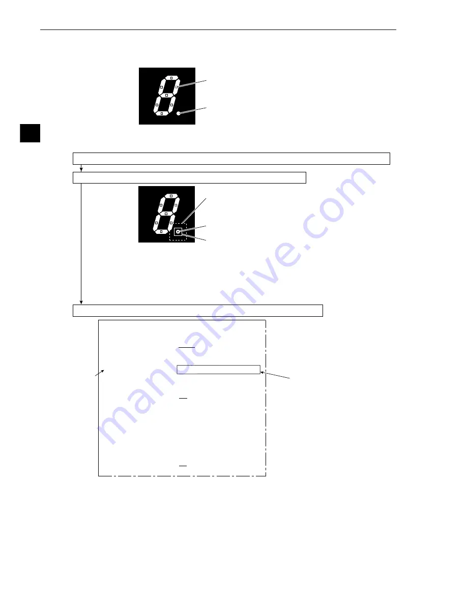
Point setting
Decimal point
Search window
Decimal point (positioning mark)
Image window
3-7 Position correction (example of point measurement)
In the setting example shown in section 3-6 "Existence inspection by point measurement," points were set
on the segment of number display (the object to be measured), and the each of the points was checked for
the correct condition.
However, the object to be measured is not always located exactly at the preset points. To deal with this
problem, use the position correction function. Then, the preset coordinates of the points are corrected
according to positional deviation of the actual object, and the measurement can be carried out correctly.
(1) Set the points using item (1) to (10) in section 3-6 "Existence inspection by point measurement"
(2) Using the decimal point in a 7-segment display as a positioning mark
- Move the reference point as described in items (1) to (10), in section 3-2 "Position
measurement."
After the setting, move the cursor to [SET-SCRN] on the MAIN OPS MENU, and press the
SET key.
-
The [SYSTEM SETUP] menu will be displayed. Move the cursor to
2
OBJECT TYPE
COND (conditions of object type) and press the SET key.
-
The [OBJECT TYPE COND] menu will be displayed.
(3) Operation on the [OBJECT TYPE COND] (conditions of object type) menu
1. Move the cursor to
5
POS. ADJ.CAMERA1 (position correction) with the up and down keys,
and press the SET key.
2. Move the cursor to REG.0-1PNTSXY (registration: 0-1, first point: XY) with the right, left, up
and down keys, and press the SET key. (Correction of X-Y coordinates).
3. Move the cursor to
u
UPPER MENU with the up and down keys, and press the SET key.
-
The [SYSTEM SETUP] menu will be displayed. Move the cursor to
0
OPERATIONS with
the up and down keys, and press the SET key.
-
The MAIN OPS MENU will be displayed.
This completes the settings for position correction using a deviation measurement. Run the
program, and the preset point coordinates will be moved according to the actual position of the
decimal point. Then the point inspection will be conducted.


