11
11-21
Setting the Input/Output Conditions
■
Response
:
1 1
Object
type
Output evaluation
results
RC
(H)
RC
(L)
Y15
Measurement 0
Measurement 0
Y1
…
Y0
SC
(H)
SC
(L)
CR
1
Data in the
specified
block
Measurement 1
Measurement 2
Measurement 3
Camera 1
data
2
Camera 2
data
2
Camera 1 Camera 2
Data from
measurement 1
data
2
Data from
measurement 2
data
2
Data from
measurement 3
data
2
[OBJECT TYPE I/O]
1
MONITOR LIGHT LVL
CAM1(1~2) NO
YES
2
LIGHT LEVEL COND
(TO NEXT SUB-MENU)
3
TRIGGER CCD START REG.NO
YES(BIN AVG-LIT-LVL)
4
CCD TRIGGER COND (TO NEXT SUB-MENU)
5
COMPUTER
LINK OUT BLOCK-00(MESR-O CMR01)
&SERIAL OUTPUT
6
SHUTTER SPEED
1/00060(1/30~1/10000)
7
STORE REF IMAGE
MOVE UP.L(224,208) LO.R (287, 271) REG. DISP
8
UPPER MENU
1
2
On the [MAIN OPS MENU], move the cursor to SET-SCRN, and press the SET key.
-
On the [SYSTEM SETUP] menu, move the cursor to item
2
OBJECT TYPE COND
and press the SET key.
-
On the [OBJECT TYPE COND] menu, move the cursor to item
t
SYSTEM IN/OUT
and press the SET key.
[2] Setting (operating) procedure
1. Move the cursor to item
5
COMPUTER LINK OUT & SERIAL OUTPUT with the up and
down keys, and press the SET key.
2. Enter the program No., camera No. and block No. of the measurement data to be output,
using the left, right, up and down keys.
- Specify a block number to be returned in addition to block 0 (00).
If block 00 is specified, data from block 00 will not be returned a second time.
3. After the settings are complete, press the SET key.
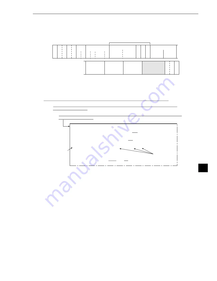
(2) When the measurement is started by a CCD trigger or a parallel I/F signal and the results
are output by a general purpose serial I/F signal
When the IV-S20 responds, data in a specified block is output after the output data (block 0) from
the measurement No. 0 to 3, in response to the measurement run command 2 (processing code
11
(H)
).
- See page 13·5 for details about
1
and
2
.
Note: The response returned by the measurement run command 2 (processing code 11
(H)
) will
not contain the specified block.


