28
System overview
System fan module
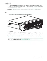
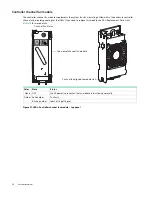
Enclosure cooling is provided by four system fan modules used in combination with two controller channel fan modules.
The IOM provides fan and LED control. This section describes system fan modules. See also
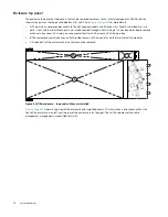
Figure 16 LEDs: System fan module – rear panel
Multiple system fan modules
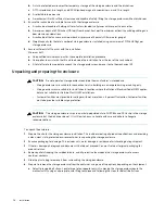
The 4U106 enclosure includes four system fan FRUs which provide redundant cooling for the system, so that if one
module fails, the others maintain airflow circulation, and enclosure operation is not affected while you replace the faulty
module. Within this FRU module, if one of the two internal rotors fails, then a fault occurs, indicating module failure. A
dual rotor failure is reported as a dual-fault. Refer to FRU Replacement Time Limit (
) for maximum allowable time
to replace FRUs. See section
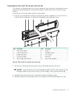
“Replacing a system fan module” (page 82)
“Replacing a controller fan module”
for replacement instructions.
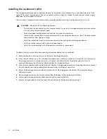
IMPORTANT:
Operation of the enclosure with any modules missing disrupts the airflow, and the drives do not receive
sufficient cooling. It is essential that all slots are fitted with system fans prior to powering on the enclosure.
Color
State
Status
None
OFF
No AC power is present or the system fan module is functioning normally. Fan activity
indicates AC power is present.
Amber Solid amber
Fan fault
Blinking amber
Ident bit is getting set
System fan oriented for use in rear panel slot
System fan status LED


