Enclosure Configuration
15
Enclosure Configuration
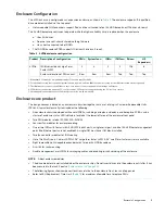
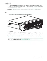
The 4U106 chassis is configured as an expansion enclosure, as shown in
. The enclosure supports 106 qualified
drive modules installed via the top panel.
•
Hot-swappable (HS) expanders support 96 disc drives attached to four 24 HDD baseplanes (12 drives x 8 rows).
The 24 HDD baseplane continues to operate while the high-availability card is replaced when the enclosure:
Uses SAS drives
Does not use split-chassis shared-nothing firmware
Has a host connected to both IOMs
•
The 10 HDD baseplane PCBA supports 10 drives (2 drives x 5 rows).
1-Redundant PSUs must be compatible modules of the same type (both AC).
2-For adequate cooling, four rear-panel system fans are required, and two IOM fans provide cooling for the IOMs (accessed via the top panel).
3-The IOM is used to connect the 4U106 to a host, or to connect to a host and additional storage enclosures.
4-LFF drives are supported using the 3.5" tool-less carrier; SFF drives are supported using the 2.5" tool-less carriers.
5-Hot-swappable expanders support 24 drive slots per drive row (8 rows total).
Enclosure core product
The design concept is based on an enclosure subsystem together with a set of plug-in Customer Replaceable Units
(FRUs). A typical enclosure System includes the following:
•
An enclosure chassis equipped with several PCBAs, including a midplane, sideplane, and baseplane PCBAs, and a
cluster of enclosure status LED indicators located at the lower left area of the enclosure front panel
•
Two PSU modules rated at 2,000W 200–240VAC
•
Four rear fan modules for enclosure cooling
•
One or two IOMs with four mini-SAS HD (SFF-8644) ports, a single serial port, and dual RJ-45 Ethernet management
ports (the Ethernet ports are not enabled). A single IOM must have IOM blank installed.
•
Two fan controller modules for IOM cooling
•
Up to 106 Disc Drive in Carriers (DDICs). 3.5” Large form factor (LFF) & 2.5” small form factor carrier are available
•
Eight removable hot-swappable expander cards, two per 24 HDD baseplane
•
A rail kit for rack mounting.
•
A cable management arm (CMA) for managing cables, and enabling in-rack servicing of the enclosure.
NOTE:
About enclosure modules
•
The drive modules are not installed when the enclosure ships. Do not insert drives into the enclosure until after it has
been secured in the rack. See also
•
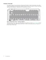
The following figures show component locations relative to the enclosure front, rear, and top panels.
•
Refer to FRU Replacement Time Limit (
) for maximum allowable time to replace FRUs.
Table 2
4U106 enclosure configuration
Product
Description of configuration
PSUs
1
System fans
2
IOMs
3
IOM fans
2
Drives
4
HS
Expanders
5
4U106
12Gb/s direct dock Large Form
Factor (LFF)
2
4
2
2
106
8
Enclosure location of FRU variant
Rear
Rear
Rear
Top
Top
Top


