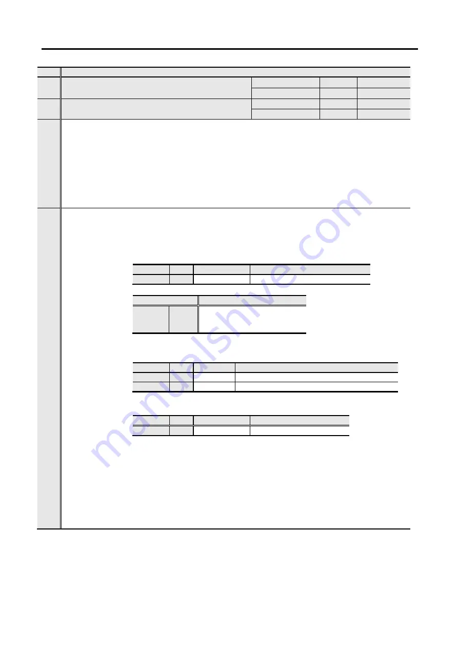
Sanyo Denki Sanmotion R 3E S Скачать руководство пользователя страница 216

5. Operation 


5-93 

Group8


ID 

Contents 

37 

Forward Direction Internal Torque Limit Value 
[TCLM-F] 

Setting range 

Unit 

Default 

10.0 to 500.0 

100.0 

38 

Reverse Direction Internal Torque Limit Value 
[TCLM-R] 

Setting range 

Unit 

Default 

10.0 to 500.0 

100.0 


Limits the Torque output at this setting value when Preset torque limit value is valid.     

  Limits the torque by the ratio for the torque rating (100.0%= torque rating)     

  When the Torque Limit Function (TL) is valid, the torque output is limited by the Preset 

torque limit setting value appropriate to the polarity of the Torque command.     

  When the following conditions are set, the torque output is limited by a rate of "Peak 

armature current at stall (IP) / Rated armature current (IR)". 


- In case of exceeding Peak torque at stall (Tp) of combination motor. 
- In case of setting of exceeding a rate of "Peak armature current at stall (IP) / Rated 
armature current (IR)". 


About Torque limit function 

There are two input systems of restricting Torque function:   
Preset torque limit and External torque limit.     


  To use preset torque limit     

  Restricts the maximum output torque by using preset torque limit.     


  Sets torque limit value.     


  Sets torque limit function ON 


Selects to set the Torque function being valid. 
While the Torque limit function is valid, restricts torque. 


When setting, be cautious about acceleration/deceleration time. If the setting value is 
too small, enough Acceleration/Deceleration torque can not get, and normal operation 
can not get.     


Set at: Preset torque limit value > Acceleration/Deceleration torque.     


Preset torque limit can set individually to Forward and Reverse direction.     


Group 

ID 

Symbol 

Contents 

36 

TLSEL 

Torque Limit Input Selection 

Selection 

Contents 

00 

TCLM

Use preset torque limit value
Forward side/TCLM-F 
Reverse side/TCLM-R 

Group 

ID 

Symbol 

Contents 

37 

TCLM-F

Forward Direction Internal Torque Limit Value

38 

TCLM-R

Reverse Direction Internal Torque Limit Value

Group 

ID 

Symbol 

Contents 

32 

TL 

Torque Limit Function 

Содержание Sanmotion R 3E S

Страница 1: ...M0010630G For Rotary Motor Instruction Manual Analog Pulse Input Type ...

Страница 2: ......

Страница 3: ... 2 15 Calorific value of R1AA18750L is changed to 365 from 355 p 4 32 4 33 Below note is added For MCCB Noise filter Magnetic contact required current per axis is describing p 5 14 Section of 3 System parameters setting list related to motor encoder due to encoder types each is added p 5 29 5 36 ID4C is added p 5 29 5 39 ID70 71 73 74 and 77 are added p 5 50 Setting ranges in general parameter Gro...

Страница 4: ...3 3 Correspondence table of EnDat Error message alarm code is added p 8 42 Note is added to clarify encoder clearing method Method of A6 Battery less absolute encoder is changed as below Power cycle Alarm reset after Encoder clear p 10 18 Period of confirmation of function operation is changed to every 3 month from annually p 12 49 Section 12 6 7 Servo motor power cable is added ...

Страница 5: ... hazards that will probably cause severe bodily injury or death as a result of incorrect operation Denotes immediate hazards which will probably cause severe bodily injury or death as a result of incorrect operation Denotes hazards which could cause bodily injury and product or property damage as a result of incorrect operation Caution Even those hazards denoted by this symbol could lead to a seri...

Страница 6: ...ound terminal should always be grounded to the unit or control board The ground terminal of the motor should always be connected to the protective ground terminal of the amplifier Electric shock could otherwise result Do not touch the inside of the amplifier Electric shock could otherwise result Do not damage the cable do not apply unreasonable stress to it do not place heavy items on it and do no...

Страница 7: ...essive heat Burn could otherwise result In terms of designing safety systems using the Safe Torque Off function personnel who have expertise of relevant safety standard are supposed to do that job with good understanding of this instruction manual Injury or damage to the device could otherwise result Please read the User Manual carefully before installation operation maintenance or inspection and ...

Страница 8: ... stored for a period of 3 years or longer Confirmations such as bearings and the brakes are necessary Transportation Caution When handling or moving this equipment do not hold the device by the cables the motor shaft or detector portion Damage to the device or bodily injury could otherwise result Keep in mind that it is dangerous at the time of conveyance if it falls and overturns Bodily injury co...

Страница 9: ...he User Manual regarding the required distance inside the amplifier disposition Fire or damage to the device could otherwise result Open the box only after checking its top and bottom location Bodily injury could otherwise result Verify that the products correspond to the order sheet packing list Injury or damage could result Take care of falling or overturning of the device during installation Us...

Страница 10: ...his action will cause faulty operation Must add the surge absorbing diode if inductive load as relay connect to the control signal output of the amplifier Please take care of polarity of the diode that will be cause of failure Do not connect DC90V or AC power to the DC24V Brake of the servo motor Also do not connect AC400V to the AC200V Fan of the servo motor An electrical short or fire could othe...

Страница 11: ...fety Next reset the alarm and restart the device Bodily injury could otherwise result Check that input power supply voltage is keeping a specification range Damage to the device could otherwise result Avoid getting close to the device as a momentary power outage could cause it to suddenly restart although it is designed to be safe even in the case of a sudden restart Bodily injury could otherwise ...

Страница 12: ...result Avoid frequent on and off power supply Inner parts might get premature failure in case of repeating ON OFF of power supply 30 times or more per day otherwise 5 times or more per hour Mandatory Install an external emergency stop circuit that can stop the device and cut off the power instantaneously Install an external protective circuit to the amplifier to cut off the power from the main cir...

Страница 13: ... result Please contact your distributor or sales office if repairs are necessary Disassembly could render the device inoperative Damage to the device could otherwise result Prohibited Do not overhaul the device Fire or electric shock could otherwise result Do not measure the insulation resistance and the pressure resistance Damage to the device could otherwise result Absolutely do not unplug the c...

Страница 14: ...olding brake 2 3 2 1 6 Degree of decrease rating for R2AA motor with oil seal and brake 2 5 2 2 Motor encoder 2 6 2 2 1 Absolute encoder 2 6 2 2 2 Incremental encoder specifications 2 7 2 2 3 Battery specification 2 7 2 3 Servo amplifier 2 8 2 3 1 General specifications 2 8 2 3 2 Input command position signal output general input general output 2 9 2 3 3 Torque limit input 2 10 2 4 Power supply ca...

Страница 15: ...tion and location 3 3 3 1 4 Arrangement within the cabinet 3 3 3 2 Servo motor 3 4 3 2 1 Precautions 3 4 3 2 2 Unpacking 3 4 3 2 3 Installation 3 4 3 2 4 Mounting method 3 5 3 2 5 Waterproofing and dust proofing 3 5 3 2 6 Protective cover installation 3 6 3 2 7 Gear installation and Integration with the target machinery 3 6 3 2 8 Allowable bearing load 3 8 3 2 9 Cable installation considerations 3...

Страница 16: ... 2 1 Check of installation and wiring 5 18 5 2 2 Check of operation 5 18 5 2 3 Check of I O signal 5 19 5 2 4 Check of device operation 5 21 5 3 Servo amplifier status display 5 22 5 3 1 Normal display 5 22 5 3 2 Alarm display 5 22 5 4 Operation sequence 5 23 5 4 1 The operation sequence with factory setting from turn power on to turn power off 5 23 5 4 2 Stop sequence at alarm 5 25 5 4 3 Sequence...

Страница 17: ...results 6 16 6 4 Manual tuning function 6 17 6 4 1 Servo system configuration and servo adjustment parameters 6 17 6 4 2 Basic manual tuning method for velocity control 6 19 6 4 3 Basic manual tuning method for position control 6 19 6 5 The function of making servo gain higher 6 20 6 5 1 Velocity loop phase lead compensation 6 20 6 5 2 Position loop phase lead compensation 6 21 6 5 3 Torque feed f...

Страница 18: ...rameters 7 12 7 5 2 Editing general parameters 7 13 7 6 How to tune automatic notch frequency 7 15 7 7 Auto FF vibration suppression frequency tuning 7 16 7 8 Offset adjustment of velocity torque command 7 17 7 9 Offset adjustment of analog torque compensation command 7 18 7 10 Velocity controlled JOG Operation 7 19 7 11 Encoder Clear 7 20 7 12 Automatic tuning result writing 7 20 7 13 Motor origi...

Страница 19: ...9 6 9 1 5 2 System parameter setting 9 7 9 1 5 3 Full closed encoder selection 9 8 9 1 5 4 Feedback pulse setting 9 9 9 1 5 5 Rotation direction setting for servo motor 9 13 9 1 5 6 Encoder output pulse signal setting 9 14 9 1 5 7 Dual position feedback compensation setting 9 15 9 1 5 8 Alarm detection setting 9 16 9 1 5 9 External encoder signal output waiting function setting 9 17 9 1 6 Precauti...

Страница 20: ...eria 10 18 10 7 Safety precautions 10 19 11 Selection 11 1 Servo motor sizing 11 1 11 1 1 Flowchart of servo motor sizing 11 1 11 1 2 Make an operation pattern 11 2 11 1 3 Calculate motor shaft conversion load moment of inertia JL 11 2 11 1 4 Calculate motor shaft conversion load torque TL 11 3 11 1 5 Calculate acceleration torque Ta 11 5 11 1 6 Calculate deceleration torque Tb 11 5 11 1 7 Calcula...

Страница 21: ... 130mm 12 7 12 3 3 R1 motor flange size 180mm 12 7 12 3 4 R2 motor flange size 40mm 60mm 80mm 86mm 100mm 12 8 12 3 5 R2 motor flange size 130mm 0 5kW to 1 8kW 12 10 12 3 6 R2 motor flange size 130mm 2kW 12 10 12 3 7 R2 motor flange size 180mm 3 5kW to 7 5kW 12 11 12 3 8 R2 motor flange size 180mm 11Kw 12 12 12 3 9 R2 motor flange size 220mm 5kW 12 12 12 3 10 R2 motor flange size 220mm 7kW to 15kW ...

Страница 22: ...egenerative resistor 12 55 12 7 Optional parts dimensions 12 56 12 7 1 Battery peripherals dimensions 12 56 12 7 2 Monitor box outline drawing 12 61 12 7 3 Dedicated Cable outline drawing 12 61 12 7 4 Outline drawing of USB communication cable 12 62 12 7 5 Outline drawing of communication cable of tandem operation between amplifiers 12 62 12 7 6 Outline drawing of regenerative resistor 12 63 ...

Страница 23: ...2 Features of SANMOTION R 3E Model 1 2 1 1 3 Cautions for replacement from SANMOTION R ADVANCED MODEL 1 3 1 2 Instruction manual 1 5 1 2 1 Contents 1 5 1 2 2 Precautions related to these instructions 1 6 1 3 Illustration of system components 1 7 1 4 Model number structure 1 11 1 4 1 Servo Motor Model Number 1 11 1 4 2 Servo Amplifier Model Number 1 13 1 5 Part names 1 16 1 5 1 Servo amplifier 1 16...

Страница 24: ... supply single axis type servo amplifier consisting of eight 8 models according to capacity This product is corresponded the Rotary Motor R series and allows using an absolute encoder and incremental encoder as motor encoder It is also allows using an incremental encoder and Heidenhain made absolute encoder Endat 2 2 as external encoder of full closed system Battery for the motor encoder is able t...

Страница 25: ...igh safe performance 2 Eco Efficient Lower power consumption Up to 10 loss reduction by equipping new generation power device And decreasing waste of energy by controlling speed of fan that cools depending on load condition and environment temperature Especially standby power requirement at servo off is decreased 10 maximum and fan noise decreased also Power consumption visualization Power consump...

Страница 26: ...line driver allowable command pulse signal is having restriction And when open collector output is used wiring change is needed See detail below Pulse output circuit of upper controller Wiring compatibility Restriction condition Differential output type line driver Yes Voltage difference of differential signal VT 2 5 to 3 8 V Open collector output type No See drawing below Saturation voltage of tr...

Страница 27: ...R ADVANCED MODEL SETUP SOFTWARE is not able to use Please download SANMOTION MOTOR SETUP SOFTWARE from our Website And prepare commercial USB cable Amplifier side is mini USB as communication cable between the setup software and amplifier General output circuit of upper controller Wiring compatibility Remarks Differential output type line driver Please change to open collector type Open collector ...

Страница 28: ... operation sequence test operations and parameters Chapter 6 Servo Tuning Explanation of servo adjustment as auto tuning manual tuning Chapter 7 Digital Operator Explanation of the LED display and use of the digital operator Chapter 8 Maintenance Explanation of troubleshooting when alarms occur and inspection Chapter 9 Dedicated function Explanation of full closed control tandem operation function...

Страница 29: ...Permission is granted to reproduce or omit a portion of the attached figures as abstracts for use The contents of this manual may be modified without prior notice as revisions or additions are created regarding the usage method of the product Modifications are performed as per the revisions of this manual Although the manufacturer has taken all possible measures to ensure the veracity of the conte...

Страница 30: ...itoring through communication with a PC Host equipment Switches power On Off Please place safeguard circuit T S R Electromagnetic contactor Brake power source SANMOTION R 3E Model Motor encoder Motor power USB Servo motor 1 3 Illustration of system components RS3 01 02 03 05 Used in case of insufficient capacity such that may be caused by high frequency of use although internal regenerative resist...

Страница 31: ...otor with brake RS3A70 Noise filter Wiring breaker MCCB T S R Switches power On Off Please place safeguard circuit External regenerative resistor Built in regenerative resistor Shot circuits RB4 RB1 External regenerative resistor Remove short bar RB4 RB1 Connect the register to RB1 RB2 Normally built in regenerative resistor of servo amplifier is used for operation An external regenerative resisto...

Страница 32: ...ervo motor with brake RS3A10 15 Noise filter Wiring breaker MCCB T S R Brake power source Built in regenerative resistor Shot circuits RB4 RB1 External regenerative resistor Remove short bar RB4 RB1 Connect the register to RB1 RB2 Switches power On Off Please place safeguard circuit Normally built in regenerative resistor of servo amplifier is used for operation An external regenerative resistor i...

Страница 33: ...ase place safeguard circuit T S R Electromagnetic contactor Wiring breaker MCCB Installed to protect power line from external noise Used to protect power line Turns off the power supply when overload runs RS3A30 Setup software Enables parameter setup and monitoring through communication with a PC Motor encoder An external regenerative resistor is used in case of insufficient capacity such as may b...

Страница 34: ...000min 1 H 3000 3500min 1 V 3000min 1 D 4000 4500 5000min 1 F 6000min 1 Existence and spec for securing brake X No brake B With brake DC90V C With brake DC24V Encoder type H Single turn absolute encoder P Battery backup absolute encoder R Battery less absolute encoder W Resolver type battery less absolute encoder S Wire saving incremental encoder See page 1 12 for kind of applicable motor encoder ...

Страница 35: ...gle turn absolute encoder PA035S H 131072 17bit Half duplex asynchronous 2 5Mbps Battery backup absolute encoder PA035C P 131072 17bit 65536 16bit Half duplex asynchronous 2 5Mbps Battery less absolute encoder HA035 R 131072 17bit 65536 16bit Half duplex asynchronous 2 5Mbps Resolver type battery less absolute encoder RA035 W 131072 17bit 65536 16bit Half duplex asynchronous 2 5Mbps Incremental en...

Страница 36: ...afe Torque Off function for detail of Safe Torque Off function RS3 A 0 Servo amplifier series RS3 SANMOTION R 3E Model series Input voltage A AC200V E AC100V Servo Amplifier capacity 01 10A 02 20A 03 30A 05 50A 07 75A 10 100A 15 150A 30 300A See page 1 14 for servo amplifier capacity and combination motor Servo Motor type A Rotary motor Motor Encoder Type EN1 for motor encoder only EN2 for motor e...

Страница 37: ...150H R2AA08075F R2AAB8100H R2AA10075F R2AA13050D R2AA13050H R2AA13120B R5AA08075D R5AA08075F RS3A05 R1AA10100F R1AA10150F R1AA10200H R1AA10250H R2AAB8075F R2AAB8100F R2AA10100F R2AA13120D R2AA13120L R2AA13180H R2AA13200L RS3A07 R1AA10200F R1AA10250F R1AA13300H R2AA13180D R2AA13200D R2AA18350V Input voltage Servo amplifier model number Servo motor model number AC100V RS3E01 R2EA04003F RS3E02 R2EA04...

Страница 38: ...ype general output Current flows to output terminal from a load at output signal ON 39 to 46 B Source type general output Current flows to a load from output terminal at output signal ON 39 to 46 OUT PWR OUT1 to 8 OUT COM OUT COM Servo amplifier Host equipment 49 24 25 Load OUT PWR OUT COM Servo amplifier Host equipment 49 38 Load OUT1 to 8 ...

Страница 39: ...citor has charge even if power is OFF Do not touch power terminal during lighting There is a risk of electric shock 8 Main circuit power input CNA For input terminal of main circuit power 9 Control power input CNA For input terminal of control power 10 Regenerative resistor terminal CNA Connect the resistor between RB1 and RB2 There are two kind of regenerative resistor internal and external 11 Mo...

Страница 40: ...OFF Do not touch power terminal during lighting There is a risk of electric shock 8 Main circuit power input terminal CNA For input terminal of control power 9 Control power input CNC For input terminal of control power 10 Regenerative resistor terminal CNA Connect the resistor between RB1 and RB2 There are two kind of regenerative resistor internal and external 11 Motor power terminal CNB 12 Eart...

Страница 41: ...rge even if power is OFF Do not touch power terminal during lighting There is a risk of electric shock 8 Main circuit power input terminal For input terminal of control power 9 Control power input CNA For input terminal of control power 10 Regenerative resistor terminal Connect the resistor between RB1 and RB2 There are two kind of regenerative resistor internal and external 11 Motor power termina...

Страница 42: ... working 11 Motor power terminal 12 Earth connecting terminal 13 USB connector for PC communication PC 4 Analog monitor connector CN6 For measuring analog signal such as velocity or current with dedicated cable 14 For function expansion connector CN5 15 For I O signal connector with host equipment CN1 16 For safety features connector CN4 5 CN7 For maintenance 17 For motor encoder EN1 6 Front panel...

Страница 43: ...R1AA1815K R2 R5 servo motor 40mm to 100mm 30W to 1 0kW R2 A04 R2 A06 R2 A08 R2 AB8 R2AA10 R5AA06 R5AA08 Brake Frame Shaft Flange Servo motor power cable Brake cable Encoder cable Encoder Fan motor Frame Shaft Flange Brake Servo motor power and earth connector Encoder connector Brake connector Fan connector Encoder ...

Страница 44: ...10150 R1AA10200 R1AA10250 R1AA13300 R1AA13400 R1AA13500 R2AA13 R2AA18350 R2AA18450 R2 servo motor 180mm 5 5kW to 7 5kW R2AA18550 R2AA18750 Encoder Frame Shaft Flange Servo motor power earth and brake connector Encoder connector Brake Encoder Frame Shaft Flange Servo motor power and earth connector Brake Encoder connector Brake connector ...

Страница 45: ...811K R2 servo motor 220mm 5kW R2AA22500 Fan motor Frame Shaft Flange Servo motor power and earth connector Encoder connector Brake Encoder Fan connector Brake connector Encoder Frame Shaft Flange Servo motor power earth and brake connector Encoder connector Brake ...

Страница 46: ...1 Preface 1 23 R2 servo motor 220mm 7kW to 15kW R2AA22700 R2AA2211K R2AA2215K Encoder Shaft Flange Servo motor power and earth connector Encoder connector Brake Brake connector ...

Страница 47: ... 4 1 Main circuit power supply capacity control power supply capacity 2 11 2 4 2 Inrush current leakage current 2 13 2 4 3 Calorific value 2 14 2 5 Operation pattern 2 16 2 5 1 Time of acceleration and deceleration permitted repetition loading precaution 2 16 2 6 Position signal output 2 19 2 6 1 Positions signals by serial signals 2 19 2 6 2 Binary code output format and transfer period 2 20 2 6 ...

Страница 48: ...on Vibration classification V15 Excitation method Permanent magnet type Installation method Flange mount 2 1 2 Exterior dimensions specifications mass Refer to 12 3 Servo Motor Dimension Refer to 12 4 Servo Motor Data Sheet 2 1 3 Mechanical specifications mechanical strength working accuracy Vibration resistance Install the servo motor horizontally shown in the figure below so when vibration occur...

Страница 49: ...al α 0 02 Eccentricity of external diameter of flange on output shaft M β 0 06 80 or less 0 08 100 or over Perpendicularity of flange face to output shaft M γ 0 07 80 or less 0 08 100 or over Figures in parentheses indicate square flange dimensions in millimeters 2 1 4 Oil seal type S Type oil seal as shown in the table below is fixed to the output shaft of the servo motor This oil seal is produce...

Страница 50: ...brake excitation signal from servo amplifier In use of this signal set suitable value to Delay Time of Releasing Holding Brake GroupB ID04 BOFFDLY and Delay Time of Engaging Holding Brake GroupB ID03 BONDLY by seeing the time in the table below as reference In use of the signal from other device for holding brake excitation control also refer the time in the table below Release delay time is same ...

Страница 51: ... 92 R2AAB8100 R2AA10075F R2AA10100F R2AA13050 3 50 30 120 R2AA13120 9 0 100 130 R2AA13180 R2AA13200 12 0 140 R2AA18350 22 0 120 50 150 R2AA18450H 32 0 150 60 250 R2AA18550 42 0 150 60 250 R2AA18750H 54 9 300 140 400 R2AA1811KR 100 300 140 400 R2AA22500L 42 150 60 250 R2AA22700S 90 300 140 400 R2AA2211KB R2AA2215KB R2EA04003F 0 32 25 15 100 R2EA04005F R2EA04008F R2EA06010F 0 36 30 20 120 R2EA06020F...

Страница 52: ...g de rating ratio has to be applied to the torque characteristic in the continuous speed range Oil seal Brake Without oil seal With oil seal With no brake Degree of decrease rating 2 With brake Degree of decrease rating 1 Degree of decrease rating 2 R2AA04005F R2AA04010F R2AA06040 R2AA08075F R2EA04005F Degree of decrease rating 1 90 90 Degree of decrease rating 1 90 85 80 90 90 Release delay time ...

Страница 53: ...kwise CCW seeing from load side PS data can be confirmed by ID33 34 ABSPS in 5 5 Monitor function Name code Motor model number encoder code Resolution per rotation Single turn Multi turn part amount Multi turn Transfer method Battery less absolute encoder HA035 R 131 072 17bit 1 048 576 20bit 8 388 608 23bit 65536 16bit Half duplex asynchronous 2 5Mbps 4Mbps Single turn absolute encoder PA035S H 1...

Страница 54: ...60mm 200W model R2AA06020FCS00 Servo motor rotation direction and encoder signal phase Motor rotation direction and motor encoder signal phases are related as follows When Z Phase is at high level both Phases A and B cross the low level once every rotation 2 2 3 Battery specification Model ER3VLY produced by Toshiba Lifestyle Products Services Corporation Voltage 3 6V Servo motor rotation directio...

Страница 55: ...5 1 55 2 5 4 2 4 9 なし Note 1 Power source voltage should be within the specified range AC200V Power input type Specified power supply range AC170V to AC264V AC100VPower input type Specified power supply range AC85V to AC132V Note 2 AC200V single phase input type corresponds only to RS3 01 RS3 02 RS3 03 RS3 05 Note 3 AC100V single phase input type corresponds only to RS3 01 RS3 02 RS3 03 Specificat...

Страница 56: ...e pulse train Negative move pulse train Stage up time t1 0 1μs Stage down time t2 0 1μs Duty t3 T x100 50 Change of pulse time ts1 2μs Pulse trains with 90 phase difference Stage up time t1 0 1μs Stage down time t2 0 1μs Duty t3 T x100 50 Minimum phase difference between pulse edges t4 t5 t6 t7 250nsec Code Pulse train Stage up time t1 0 1μs Stage down time t2 0 1μs Duty t3 T x100 50 Change of pul...

Страница 57: ...bling function 5 102 for details General output Sink type general output Source type general output Sequence output Open collector output x 8 outputs Power supply for general output circuit CN1 49 OUT PWR DC5V 5 DC12V to DC24V 10 20mA or over Specification of Power supply for general output circuit DC5V 5 Maximum current value 10mA per 1 output DC12V DC15V 10 Maximum current value 30mA per 1 outpu...

Страница 58: ...0 1 0 R5AA06020F 200 0 6 R5AA06040F 400 1 0 R5AA06040H 400 1 0 RS3A03 R1AA10100H 1000 2 3 R1AA10150H 1500 3 0 R2AA08075F 750 1 6 R2AAB8100H 1000 2 0 R2AA10075F 750 1 7 R2AA13050D 550 1 2 R2AA13050H 550 1 2 R2AA13120B 1200 2 2 R5AA08075D 750 1 6 R5AA08075F 750 1 6 RS3A05 R1AA10100F 1000 2 3 R1AA10150F 1500 3 0 R1AA10200H 2000 4 0 R1AA10250H 2500 5 0 R2AAB8075F 750 1 6 R2AAB8100F 1000 2 3 R2AA10100F...

Страница 59: ...450H 4500 7 4 R2AA18550R 5500 8 4 R2AA22500L 5000 9 6 R2AA22700S 7000 12 2 RS3A30 R1AA18550H 5500 9 3 R1AA18750L 7500 11 6 R1AA1811KR 11000 16 0 R1AA1815KB 15000 21 4 R2AA18550H 5500 9 3 R2AA18750H 7500 11 6 R2AA1811KR 11000 16 0 R2AA2211KB 11000 16 0 R2AA2215KB 15000 21 4 AC100V Input Input Voltage Servo amplifier capacity Servo motor model number Rated output W Main circuit power supply kVA Cont...

Страница 60: ...3 02 0 8 mA RS3 03 0 8 mA RS3 05 1 5 mA RS3 07 3 0mA RS3 10 3 0mA RS3 15 3 0mA RS3 30 3 0mA Optional alphabetical letter Leakage current value above is measured by leak checker which has set 700 Hz filter While using two 2 or more motors leakage current from each motor should be added These values are applicable when a tough rubber sheath cable of 2M is used as a power line In the case of a shorte...

Страница 61: ...A06040H 22 RS3A03 R1AA10100H 45 R1AA10150H 60 R2AA08075F 43 R2AAB8100H 45 R2AA10075F 43 R2AA13050D 44 R2AA13050H 40 R2AA13120B 50 R5AA08075D 43 R5AA08075F 43 RS3A05 R1AA10100F 60 R1AA10150F 70 R1AA10200H 70 R1AA10250H 80 R2AAB8075F 45 R2AAB8100F 52 R2AA10100F 50 R2AA13120D 68 R2AA13120L 60 R2AA13180H 87 R2AA13200L 87 RS3A07 R1AA10200F 100 R1AA10250F 115 R1AA13300H 120 R2AA13180D 110 R2AA13200D 100...

Страница 62: ...L 164 R2AA22700S 235 RS3A30 R1AA18550H 315 R1AA18750L 365 R1AA1811KR 430 R1AA1815KB 450 R2AA18550H 315 R2AA18750H 365 R2AA1811KR 430 R2AA2211KB 440 R2AA2215KB 450 Input voltage Servo amplifier capacity Servo motor model number Servo amplifier total calorific value W AC100V RS3E01 R2EA04003F 13 RS3E02 R2EA04005F 15 R2EA04008F 16 R2EA06010F 17 RS3E03 R2EA06020F 26 Optional alphabetical letter Calori...

Страница 63: ...on repetitive operations for both the servo motor and servo amplifier and the conditions of both must be met simultaneously Frequency of permitted repetitions for the servo amplifier When Start Stop sequences are repeated frequently confirm in advance that the frequency of repetitions are within tolerance range Allowed repetitions differ depending on the type capacity load inertia moment accel dec...

Страница 64: ...riate in the above formula are required When actually determining the system drive mode it is recommended to calculate the load margin and suppress it to Trms 0 8TR When the motor repeats acceleration deceleration and stop status In operating status shown below the value of permitted repetitions n times minutes is found with the following equation TP Peak Torque at stall N m TR Rated torque N Moto...

Страница 65: ...hen there is no center weight Using like a generator such as the wind out spindle of a winder Load inertia moment JL When the servo amplifier is used with a load inertia moment exceeding the allowable load inertia moment calculated in terms of the motor shaft main circuit power over voltage detection or regenerative error function may be issued at the time of the operation Reduce the torque limit ...

Страница 66: ...synchronous Baud rate 9600bps 9600bps Format 11bit 10bit Transmission error check 1bit Even number parity 1bit Even number parity Transfer time Typ 9 2ms 16 7ms Transfer period Approximately 11ms Approximately 40ms Increase method Increase during forward operation Increase during forward operation Encoder signal output PS outputs from CN1 9 10pin Will be Motor encoder direct output when 02 Mot_Dir...

Страница 67: ... the single multi turn dividing number and the data position Single turn Multi turn Data within 1 rotation Data within multiple rotations 17bit None D0 to D16 17bit 16bit D0 to D16 D17 to D32 20bit 16bit D0 to D19 D20 to D35 23bit 16bit D0 to D22 D23 to D38 Unused data bit will be zero Transfer period The signal is indefinite for about 2 seconds after booting power and communication may not always...

Страница 68: ... digit 0 1 1 Data 14 0 1 rotation data 2nd digit 0 1 1 Data 15 0 1 rotation data 1st digit 0 1 1 Data 16 0 Carriage return CR 0 1 1 Relation of the single multi turn dividing number and the data position Single turn Multi turn Data within 1 rotation Data within multiple rotations 17bit None 0000000 to 0131072 17bit 16bit 0000000 to 0131072 00000 to 65535 20bit 16bit 0000000 to 1048576 00000 to 655...

Страница 69: ...ion of Phase Z or Phases A B When other than 1 1 is set as division ratio Phase A and Phase B are divided but Phase Z is output with original pulse width Absolute encoder can output the frequency up to 2Mpulse sec multiplied one When EnDat is used in external encoder with full closed control Phase Z is output every 8192 pulses multiplied one based on absolute position 0 EnDat angle encoder rotary ...

Страница 70: ... on board DF11 4DP 2DSA 01 Housing model number on receiving equipment DF11 4DS 2C Connector model number on receiving equipment DF11 2428SCA General input output connector CN1 CN6 Analog monitor output 1 MON1 CN1 30 CN6 3 Analog monitor output 2 MON2 Disabled CN6 4 Digital monitor output DMON Disabled CN6 2 GND CN1 31 CN6 1 CN6 4 2 3 1 ...

Страница 71: ...itor output Output voltage 2V 1000min 1 Reverse rotation Forward rotation 2V 0 1000min 1 Output voltage 2V 1000min 1 Reverse rotation Forward rotation 2V 0 1000min 1 Output voltage 2V 1000min 1 Reverse rotation Forward rotation 0 1000min 1 Without polarity inversion With polarity inversion ABS Absolute value output Output voltage 2V TR Reverse rotation Forward rotation 2V 0 TR Output voltage 2V TR...

Страница 72: ...verheat alarm of the dynamic break or failure of dynamic brake resistance Please consult us if such a situation is evident Instantaneous tolerance of dynamic brake Servo amplifier model number ERD J RS3 02A A RS3 02A L 218 RS3 03A A RS3 03A L RS3 05A A RS3 05A L 912 RS3 07A A RS3 07A L 2000 RS3 10A A RS3 10A L 2450 RS3 15A A RS3 15A L RS3 30A L 9384 Optional number or alphabetical letter RS3 01A d...

Страница 73: ... 4 R5AA06040F 10 11 1 55 10 6 0 416 10 4 R5AA06040H 6 09 2 3 10 6 0 416 10 4 RS3A03 R1AA10100H 2 6 1 21 10 6 1 4 10 4 R1AA10150H 1 31 6 87 10 7 2 0 10 4 R2AA08075F 5 84 9 10 10 8 1 82 10 4 R2AAB8100H 3 09 3 83 10 7 2 38 10 4 R2AA10075F 6 04 1 2 10 6 2 0 10 4 R2AA13050D 6 46 2 14 10 6 3 1 10 4 R2AA13050H 4 37 3 55 10 6 3 1 10 4 R2AA13120B 1 68 1 56 10 6 6 10 4 R5AA08075D 4 67 1 67 10 6 1 65 10 4 R5...

Страница 74: ...18450H 0 67 1 2 10 8 50 10 4 R2AA18550R 0 53 7 10 9 68 10 4 R2AA22500L 0 8 0 41 10 7 55 10 4 R2AA22700S 0 16 7 10 9 136 10 4 RS3A30 R1AA18550H 1 08 4 10 9 33 10 4 R1AA18750L 0 67 2 10 9 42 10 4 R1AA1811KR 0 41 2 10 9 64 10 4 R1AA1815KB 0 26 2 10 9 86 10 4 R2AA18550H 1 13 4 10 9 68 10 4 R2AA18750H 0 72 2 10 9 98 10 4 R2AA1811KR 0 51 3 10 9 110 10 4 R2AA2211KB 0 42 1 10 9 178 10 4 R2AA2215KB 0 35 1 ...

Страница 75: ...egenerative resistor RS3 01A A 50Ω 35Ω RS3 02A A 50Ω 35Ω RS3 03A A 50Ω 35Ω RS3 05A A 17Ω 17Ω RS3A07A A RS3A07A L 10Ω 10Ω RS3A10A A RS3A10A L 10Ω 10Ω RS3A15A A RS3A15A L 6Ω 6Ω RS3A30A L without built in regenerative resistor 2 5Ω is optional number or alphabetical letter 2 9 2 Allowable regenerative power Servo amplifier model Built in regenerative resistor use PRI External regenerative resistor us...

Страница 76: ...No Text on This Page ...

Страница 77: ...cation 3 3 3 1 4 Arrangement within the cabinet 3 3 3 2 Servo motor 3 4 3 2 1 Precautions 3 4 3 2 2 Unpacking 3 4 3 2 3 Installation 3 4 3 2 4 Mounting method 3 5 3 2 5 Waterproofing and dust proofing 3 5 3 2 6 Protective cover installation 3 6 3 2 7 Gear installation and Integration with the target machinery 3 6 3 2 8 Allowable bearing load 3 8 3 2 9 Cable installation considerations 3 10 ...

Страница 78: ...d the servo amplifier does not exceed 55 C For longevity and reliability purposes it is recommended to keep the temperature below 40 C If there is a vibration source nearby Protect the servo amplifier from vibration by installing it on a base with a shock absorber If there is a heat generator nearby If the ambient temperature might increase by convection or radiation make sure the temperature near...

Страница 79: ...vo amplifier is the same as ordered The model number is located on the main nameplate following the word MODEL Verify that there is no problem in the appearance of servo amplifier Verify that there are no loose screws on the servo amplifier Interpretation of the serial number Month 2 digit Year 2 digit Day 2 digit Serial number 4 digit Revision A abbreviated Servo amplifier Servo amplifier main na...

Страница 80: ...purposes it is recommended to keep the temperature below 40 C Leave at least 10 mm space on both sides of the servo amplifier to ensure unobstructed airflow from the heat sinks on the side and from the inside of the servo amplifier For RS3 02 RS3 03 RS3 05 a cooling fan is attached at the side Therefore it is recommended that the servo amplifier be mounted in an arrangement as shown below Arrangem...

Страница 81: ... motor is the same as ordered The model number is located on the main nameplate following the word MODEL Verify that there is no problem in the appearance of servo motor Verify that there are no loose screws on the servo motor 3 2 3 Installation Please note the following regarding the installation location and mounting method The servo motor is designed for indoor use Make sure to Install it indoo...

Страница 82: ...tlet should be installed facing downwards as nearly vertical as possible In vertical installation create a cable trap to prevent oily water from getting into the motor 3 2 5 Waterproofing and dust proofing The protection inside the motor conforms to IEC standards IEC34 5 However such protection is suitable only for short term use For regular use additional sealing measures are required Be sure to ...

Страница 83: ...all the connectors lead outlets facing downwards create a sag in the cable to prevent water or oil from entering the motor 3 2 7 Gear installation and Integration with the target machinery The oil level of the gear box should be below the oil seal lip for a slight spraying effect on the lip Create a hole to prevent pressure build up inside the gear box as pressure can cause water or oil to penetra...

Страница 84: ...d hit the front flange area For mounting to a machine create accurate enough mounting holes for smooth coupling of the motor flange rabbet The mounting surface should be flat otherwise damage to the shaft or the load may occur Use the screw at the end of the shaft for installing parts such as the gear pulley or coupling to avoid shock Tapered servo motor shafts transmit the torque via the tapered ...

Страница 85: ...ion F1 Thrust load The radial load tolerance value is the maximum load that can be applied at the point measured 1 3 of the distance from the tip of the output shaft Servo motor model number Assembly Operation Radial load N Thrust load N Radial load N Thrust load N FR Direction F Direction F1 FR Direction F Direction F1 R1 R1AA10100 980 290 290 690 290 290 R1AA10150 980 290 290 690 290 290 R1AA102...

Страница 86: ...40 200 200 R2AAB8100 590 780 290 340 200 200 R2AA10075 590 780 290 340 200 200 R2AA10100 590 780 290 340 200 200 R2AA13050 980 1400 1400 640 490 490 R2AA13120 1700 1900 1900 640 490 490 R2AA13180 1700 1900 1900 640 490 490 R2AA13200 1700 1900 1900 640 490 490 R2AA18350 2300 1900 1900 1500 290 290 R2AA18450 2300 1900 1900 1500 290 290 R2AA18550 3900 2000 2000 1800 590 590 R2AA18750 3900 2000 2000 1...

Страница 87: ...pass cables through the areas having possibility that machine corner scrapes against cables or personnel machines may tread on cables Take measures such as clamp to machines so as not to apply flexion stress and own weight stress onto each connecting point of cables When motor and cables need to be transferred with cableveyor cable carrier bending radius of cable shall be determined by referring r...

Страница 88: ...No Text on This Page ...

Страница 89: ...tage circuit terminal tightening torque 4 12 4 2 Wiring with Host Unit 4 13 4 2 1 CN1 signal name and pin number wiring with host unit 4 13 4 2 2 CN1 pin assignment 4 15 4 2 3 Signal name and its function 4 15 4 2 4 Terminal connection circuit 4 16 4 3 Wiring for motor encoder 4 27 4 3 1 EN1 EN2 signal names and its pin numbers 4 27 4 3 2 EN1 EN2 pin assignment 4 29 4 3 3 Connector model number fo...

Страница 90: ... 15 50 60Hz 3 Control power supply r t Single phase AC100 to 120V 10 15 50 60Hz 3 Single phase AC200 to 240V 10 15 50 60Hz 3 Servo motor connector U V W Connected with servo motor Protective grounding terminal Connected with grounding wire of power supply and of servo motor Regeneration resistance connector RB1 RB2 RB4 RS3 01 RS3 02 RS3 03 RS3A05 RS3A30 Connects regenerative resistance to terminal...

Страница 91: ...three electric wires bundled Use wire at less than above mentioned allowable current AWG size Nominal cross sectional area mm2 Conductor resistance Ω km Allowable current over ambient temperature A 30 C 40 C 55 C 20 0 5 39 5 6 6 5 6 4 2 19 0 75 26 0 8 8 7 0 5 4 18 0 9 24 4 9 0 7 7 5 8 16 1 25 15 6 12 0 11 0 8 3 14 2 0 9 53 23 0 20 0 15 0 12 3 5 5 41 33 0 29 0 21 8 10 5 5 3 47 43 0 38 0 28 5 8 8 0 ...

Страница 92: ... wires than indicated in the above table can be used for the main circuit power terminal Servo motor model No Motor power U V W Combination servo amplifier Main circuit power supply R S T Control power supply Regenerative resistance mm2 AWG No mm2 AWG No mm2 AWG No mm2 AWG No mm2 AWG No R2AA04003F 0 5 20 RS3 01 1 25 16 1 25 16 2 0 14 2 0 14 R2AA04005F R2AA04010F R2AA06010F R5AA06020H R2AA06020F 0 ...

Страница 93: ...wer terminal Servo motor model No Motor power U V W Combination servo amplifier Main circuit power supply R S T Control power supply Regenerative resistance mm2 AWG No mm2 AWG No mm2 AWG No mm2 AWG No mm2 AWG No R2EA04003F 0 5 20 RS3 01 1 25 16 1 25 16 1 25 16 2 0 14 R2EA04005F RS3 02 R2EA04008F R2EA06010F R2EA06020F 0 75 19 RS3 03 2 0 14 2 0 14 Servo motor model No Motor power U V W Combination s...

Страница 94: ...model number Plug for powering and braking line Cable clamp type Plug clamp model number Plug for braking line Cable clamp type Plug clamp model number Straight Angle Straight Angle R1AA10100 N MS3106B20 15S N MS3057 12A MS06B20 15S 12 N MS3108B20 15S N MS3057 12A MS08B20 15S 12 Note 1 Note 1 R1AA10150 R1AA10200 R1AA10250 R1AA13300 N MS3106B24 11S N MS3057 16A MS06B24 11S 16 N MS3108B24 11S N MS30...

Страница 95: ...p model number our exclusive model numbers For wire size of cooling fan 1 25mm2 AWG16 is recommended Servo motor model number Plug model number for cooling fan Cable clamp model number Plug clamp model number Connector type Disposition symbol of pins 200V AC 10 Single phase50 60Hz All of R1 series R2AA1811K N MS3106B10SL 4S N MS3057 4A MS06B10SL 4S 4 Straight A B N MS3108B10SL 4S N MS3057 4A MS08B...

Страница 96: ...d from motor Canon plug for cooling fan Pin assignment Viewed from motor Canon plug for power line for N MS3106 8 B24 11S Pin assignment Viewed from motor Phase U Phase V Phase W Earth Canon plug for power line for N MS3106 8 B32 17S Pin assignment Viewed from motor Phase U Phase V Phase W Earth Canon plug for power line for N MS3106 8 B20 15S Pin assignment Viewed from motor Phase U Phase V Phase...

Страница 97: ...tput Sink type For ALM contact of safety circuit use one of the outputs from CN1 39 to 46 OUT1 to OUT8 as alarm signal by setting either During ALM status output ON or During ALM status output OFF at the selection setting of Group A General output terminal output condition 5 113 Must add the surge absorbing diode to if inductive load as relay connect to CN1 39 to 46 OUT1 to OUT8 Please take care o...

Страница 98: ...on 5 113 Must add the surge absorbing diode to if inductive load as relay connect to CN1 39 to 46 OUT1 to OUT8 Please take care of polarity of the diode that will be cause of failure CN1 39 46 OUT1 OUT8 24 25 49 Servo motor RB1 RB2 M T U S R r V W t CN1 39 46 OUT1 OUT8 24 25 49 Servo motor RB1 RB2 M T U S R r V W t Single phase AC200 to 240V 50 60 Hz COM DC5V DC12V 24V Operation ON OFF MC Noise fi...

Страница 99: ...p A General output terminal output condition 5 113 Must add the surge absorbing diode to if inductive load as relay connect to CN1 39 to 46 OUT1 to OUT8 Please take care of polarity of the diode that will be cause of failure Single phase AC200 240V 50 60 Hz CN1 39 46 OUT1 OUT8 38 49 Servo motor RB1 RB2 M T U S R r V W t DC5V DC12V 24V 3 phase AC200 240V 50 60 Hz Emergency stop DC5V DC12V 24V CN1 3...

Страница 100: ...FF at the selection setting of Group A General output terminal output condition 5 113 Must add the surge absorbing diode to if inductive load as relay connect to CN1 39 to 46 OUT1 to OUT8 Please take care of polarity of the diode that will be cause of failure Single phase AC200 to 240V 50 60 Hz CN1 39 46 OUT1 OUT8 38 49 Servo motor RB1 RB2 M T U S R r V W t DC5V DC12V 24V Emergency stop MC Noise f...

Страница 101: ... mm2 AWG Model number 1Pcs Pkt 1000Pcs Pkt Taped components 0 75 mm2 19 AI0 75 8GY AI0 75 8GY 1000 AI0 75 8GY B 1000Pcs Pkt 1 0 mm2 18 AI1 8RD AI1 8RD 1000 AI1 8RD B 1000Pcs Pkt 1 5 mm2 16 AI1 5 8BK AI1 5 8BK 1000 AI1 5 8BK B 1000Pcs Pkt 2 5 mm2 14 AI2 5 8BU AI2 5 8BU 1000 AI2 5 8BU B 500Pcs Pkt 4 0mm2 12 AI4 10GY Note1 5 5mm2 10 A6 10 Note1 Note2 Terminal marking Servo amplifier model number R S ...

Страница 102: ...ring of CN1 use a twisted pair shield cable Servo amplifier AO BO ZO PS 11 ZOP SG 5V SG CONT7 15 SG 48 R PC 29 R TLA SG 17 F TLA 50 37 CONT1 CONT2 CONT COM 36 CONT3 35 CONT4 34 CONT5 33 32 CONT6 V REF T REF SG 20 T COMP SG 22 23 SG 47 F PC 38 CONT8 BTP 1 1 2 BTN 1 EN1 9 BAT EN1 10 BAT 3 4 5 6 7 8 9 10 12 OUT PWR OUT1 OUT2 OUT3 OUT4 OUT5 OUT6 OUT7 OUT8 OUT COM OUT COM 49 39 40 41 42 43 44 45 46 24 ...

Страница 103: ...output even if general outputs are used as source type Servo amplifier AO BO ZO PS 11 ZOP SG 5V SG SG 48 R PC R TLA SG 17 F TLA 50 37 CONT1 CONT2 CONT COM 36 CONT3 35 CONT4 34 CONT5 33 V REF T REF SG 20 T COMP SG 23 SG 47 F PC BTP 1 1 2 BTN 1 EN1 9 BAT EN1 10 BAT 3 4 5 6 7 8 9 10 12 OUT PWR OUT1 OUT2 OUT3 OUT4 OUT5 OUT6 OUT7 OUT8 OUT COM OUT COM 49 40 41 42 43 44 45 25 SG 30 31 MON1 24 R PC F PC B...

Страница 104: ...21 21 V REF Velocity command input T REF Torque command input 22 T COMP Torque compensation input 23 SG Common for pin 22 14 PC PWR Internal power for command pulse 16 PC PWR Internal power for command pulse 26 F PC Command pulse input 27 F PC Command pulse input 28 R PC Command pulse input 29 R PC Command pulse input 47 SG Common for pins 26 27 48 SG Common for pins 28 29 Terminal number Signal n...

Страница 105: ... Description 1 BTP 1 Battery plus 2 BTN 1 Battery minus Servo amplifier Host unit Twisted pair EN1 Servo motor Battery 1 2 Terminal No Symbol Name Description 3 AO A phase pulse output 4 AO A phase pulse output 5 BO B phase pulse output 6 BO B phase pulse output 7 ZO Z phase pulse output 8 ZO Z phase pulse output 12 SG Common for pins 3 to 11 Twisted pair A A SG HD26C31 or equivalent 3 4 5 B Z B Z...

Страница 106: ...pen collector Sink type open collector output Make sure to connect SG Source type open collector output is not available Terminal No Symbol Name Description 11 ZOP Z phase pulse output Circuit spec Max voltage DC30V Max current 10mA 12 SG Common for pins 3 to 11 Twisted pair ZOP SG 11 12 SG Servo amplifier Host unit SG VCC ...

Страница 107: ...nput voltage range 10V to 10V Input impedance about 10kΩ 19 R TLA Reverse side torque limit input 17 SG Common for pins 18 19 F TLA 10kΩ 1 8kΩ 0 01μ F SG Servo amplifier Host unit 1 8kΩ 1 0kΩ 0 01μ F 1 8kΩ 0 01μ F 1 8kΩ 1 0kΩ 0 01μ F 18 19 17 R TLA SG 10kΩ SG Terminal No Control type Symbol Name Description 21 Position V REF Velocity addition command input Circuit spec Max allowable input voltage ...

Страница 108: ...by analog voltage Make sure to connect SG Terminal No Symbol Name Description 22 T COMP Torque compensation input Circuit spec Max allowable input voltage is 10V Input impedance is about 10kΩ 23 SG Common for pins 22 T CMP 10kΩ 1 8kΩ 0 01μ F SG Servo amplifier Host unit 1 8kΩ 1 0kΩ 0 01μ F SG 22 23 Twisted pair ...

Страница 109: ... from host unit is able to choose from 3 types Differential line driver Sink type open collector and Source type open collector For Differential line driver It will be cause of wrong operation by pulse missing or circuit failure when differential output voltage VT is less than 2 5V or more than 3 8V Terminal No Symbol Name Description 26 F PC Command pulse input Differential line driver spec Choos...

Страница 110: ...mand pulse input Output transistor spec Choose host unit side transistor which has collector emitter voltage VCE range less than 1 5V 27 F PC Command pulse input 14 PC PWR Internal power for command pulse 47 SG Common for pins 26 27 28 R PC Command pulse input 29 R PC Command pulse input 16 PC PWR Internal power for command pulse 48 SG Common for pins 28 29 Servo amplifier SG 150Ω 1kΩ SG 29 Host u...

Страница 111: ... Pull up resistance spec Choose pull up resistance RX from table below with depending to power supply voltage VCC to keep range of input current to servo amplifier 3 8 to 15 mA External power VCC Pull up resistance RX 5V 5 100 to 180Ω 12V 5 590 to 1 5kΩ 24V 5 1 8k to 3 9kΩ Output transistor spec Choose host unit side transistor which has collector emitter voltage VCE range less than 1 5V 27 F PC C...

Страница 112: ...stance spec Choose pull up resistance RX from table below with depending to power supply voltage VCC to keep range of input current to servo amplifier 3 8 to 15 mA External power VCC Pull up resistance RX 5V 5 100 to 180Ω 12V 5 590 to 1 5kΩ 24 5 1 8k to 3 9kΩ Output transistor spec Choose host unit side transistor which has collector emitter voltage VCE range less than 1 5V 27 F PC Command pulse i...

Страница 113: ...ple 36 CONT2 General input 35 CONT3 General input 34 CONT4 General input 33 CONT5 General input 32 CONT6 General input 13 CONT7 General input 15 CONT8 General input 50 CONT COM For power supply to general input Sink type circuit Source type circuit Host unit CONT COM 50 37 CONT1 2 2kΩ 4 7kΩ 36 35 34 33 32 CONT2 CONT3 CONT4 CONT5 CONT6 Servo amplifier 13 15 CONT7 CONT8 Terminal No Symbol Name Descr...

Страница 114: ...PWR Power supply voltage range DC5V 5 DC12V to DC24V 10 Current capacity 20mA or more General output OUT 1 to OUT 8 spec Power supply voltage range Maximum output current Each port DC5V 5 10mA DC12 to 15V 10 30mA DC24V 10 50mA 40 OUT2 General output 41 OUT3 General output 42 OUT4 General output 43 OUT5 General output 44 OUT6 General output 45 OUT7 General output 46 OUT8 General output 49 OUT PWR F...

Страница 115: ... output OUT PWR Power supply voltage range DC5V 5 DC12V to DC24V 10 Current capacity 20mA or more General output OUT 1 to OUT 8 spec Power supply voltage range Maximum output current Each port DC5V 5 10mA DC12 to 15V 10 30mA DC24V 10 50mA 40 OUT2 General output 41 OUT3 General output 42 OUT4 General output 43 OUT5 General output 44 OUT6 General output 45 OUT7 General output 46 OUT8 General output ...

Страница 116: ...hould connect to outer shielded wire of encoder at the servomotor with leads or connect up to the edge of cannon plug at the servo motor with cannon plug This encoder does not connect outer shields to somewhere inside of the servo motor equipped with this encoder Note 3 Do not connect anything to 3 to 6 9 and 10 pins Servo Amplifier EN1 Terminal No Signal name R series Servo motor plug pin number ...

Страница 117: ...ector EN1 or EN2 and an earth of motor encoder Note 4 Do not connect anything to 3 and 4 pins Servo Amplifier EN1 Terminal No Signal name R series Servo motor plug pin number For lead wire type Description Remarks Note 1 1 5V 9 Red Power supply Twisted pair Recommended 2 SG 10 Black Power supply common 3 5V NC Note 3 4 SG NC Note 3 5 NC NC Note 3 6 NC NC Note 3 7 ES 1 Brown Serial data signal Twis...

Страница 118: ...Wirings vary depending on encoders to be connected so please carefully perform wiring Connector model number 3M Japan Limited 9 10 7 8 1 2 5 6 3 4 Model Number Applicable wire size Applicable cable diameter Connector 36210 0100PL AWG30 to AWG18 Shell kit 36310 3200 008 φ 7 to φ 9 ...

Страница 119: ...010 R2 A06010 R2 A06020 R2AA08020 R2AA06040 R2AA08040 R2AA08075 R2AAB8075 R2AAB8100 R2AA10075 R2AA10100 R5AA06020 R5AA06040 R5AA08075 Lead wire type R1AA10100 R1AA10150 R1AA10200 R1AA10250 R1AA13300 R1AA13400 R1AA13500 R1AA18550 R1AA18750 R1AA1811K R1AA1815K R2AA13050 R2AA13120 R2AA13180 R2AA13200 R2AA18350 R2AA18450 R2AA18550 R2AA18750 R2AA1811K R2AA22500 R2AA22700 R2AA2211K R2AA2215K JN2DS10SL1 ...

Страница 120: ...ngths by conductor sizes of power supply cable 5V SG The values above are for the case power supply 5V SG line is wired in a pair Conductor resistance varies depending on conductor specifications Type Model number Qty Applicable wire size Manual crimping type JN1 22 20S R PKG100 Note 1 AWG20 JN1 22 22S PKG100 Note 1 AWG21 to AWG25 JN1 22 26S PKG100 Note 1 AWG26 to AWG28 Soldering type JN1 22 22F P...

Страница 121: ... SOSHIN ELECTRIC Co Ltd S N10 MITSUBISHI ELECTRIC LV275DI U4 OKAYA ELECTRIC INDUSTRIES CO LTD R2AA04005F 0 2 R2AA04010F 0 3 R2AA06010F 0 3 R5AA06020H 0 6 RS3 02 R2AA06020F 0 6 R2AA06040F 1 0 R2AA06040H 1 0 R2AA08020F 0 6 R2AA08040F 1 0 R5AA06020F 0 6 R5AA06040F 1 0 R5AA06040H 1 0 RS3 03 R1AA10100H 2 3 R1AA10150H 3 0 R2AA08075F 1 6 R2AAB8100H 2 0 R2AA10075F 1 7 R2AA13050D 1 2 R2AA13050H 1 2 R2AA131...

Страница 122: ...fier model number Servo motor model No Main circuit power supply rating kVA Molded Case Circuit Breaker MCCB Noise filter Magnetic contact Surge absorber AC200V RS3A10 R1AA13300F 6 0 Model NF50 30A MITSUBISHI ELECTRIC 3SUPF CH 40M F OKAYA ELECTRIC INDUSTRIES CO LTD S N18 MITSUBISHI ELECTRIC LV275DI U4 OKAYA ELECTRIC INDUSTRIES CO LTD R1AA13400H 6 7 R1AA13500H 8 3 R2AA13180D 4 0 R2AA13200D 5 0 R2AA...

Страница 123: ...5 4 Operation sequence 5 23 5 4 1 The operation sequence with factory setting from turn power on to turn power off 5 23 5 4 2 Stop sequence at alarm 5 25 5 4 3 Sequence of alarm reset 5 27 5 4 4 Sequence when power is turned OFF during operation During servo ON 5 28 5 5 Monitor function 5 29 5 5 1 Monitor list 5 29 5 5 2 Descriptions of each monitor 5 30 5 6 Analog monitor and digital monitor 5 40...

Страница 124: ...1 Check for the servo amplifier spec Check by 4 items below whether your product is fit to the target system spec Motor structure Main power supply voltage Amplifier capacity code Encoder type 1 Check by the setup software Connect the servo amplifier by USB cable to a PC which installed setup software and then turn on control power r t Run the setup software and start communication with the servo ...

Страница 125: ...age Amplifier capacity and Encoder type are shown in System Information area See below Check each item above by following description of step 2 or later See the manual M0010842 for detail of the setup software operation 2 Check by the digital operator Use servo amplifier info code display function InFo 1 to 3 See 7 4 7 How to check servo amplifier info code 1 to 3 for detail of the function use ...

Страница 126: ...formation area of Axis property window 2 By the digital operator Main power supply voltage code is shown at a lower byte of InFo 1 Step 4 Check for amplifier capacity This shows servo amplifier capacity of output current Please confirm that the amplifier capacity code is match to combined motor 1 By the setup software Amplifier capacity code is shown in System Information area of Axis property win...

Страница 127: ...code is shown in System Information area of Axis property window 2 By the digital operator Encoder type code is shown at an upper byte of InFo 2 Servo amplifier model number Encoder type code The motor encoder allowed by EN1 The external encoder allowed by EN2 RS3 A0 00 Absolute encoder N A RS3 A1 01 Absolute encoder Absolute encoder RS3 A2 02 Absolute encoder Incremental encoder RS3 A8 08 Increme...

Страница 128: ...ue 5 15 10 Motor encoder input selection Selecting connector of motor encoder to use 5 11 5 13 11 EN1 encoder type Selecting encoder type of EN1 connection 5 11 5 13 12 EN2 encoder type Selecting encoder type of EN2 connection 5 13 13 EN1 absolute encoder baud rate selection Selecting communication speed of absolute encoder of EN1 connection 5 11 14 Battery backup absolute encoder function selecti...

Страница 129: ... RS3 A Input power voltage A AC200V E AC100V Option 1 A With regenerative resistor With DB reisitor L Without regenerative resistor With DB reisitor Encoder type EN1 for motor encoder only EN2 for motor encoder or external encoder 0 Absolute encoder 1 Absolute encoder Absolute encoder 2 Absolute encoder Incremental encoder 8 Incremental encoder 9 Incremental encoder Absolute encoder A Incremental ...

Страница 130: ...t_CS 22 EnDat _ABS 82 Pulse_ without_CS 13 EN1 absolute encoder baud rate selection 02 2 5Mbps 14 Battery backup absolute encoder function selection 00 Absolute_System 15 Absolute encoder resolution 06 131 072_FMT 16 Absolute encoder multi turn value 06 65 536_ROT 17 Incremental encoder resolution 2 000 2000 20 Position loop control position loop encoder selection 01 External_Enc 01 External_Enc 2...

Страница 131: ...ic set Setting by the digital operator Setting by the setup software Applicable motor Absolute encoder Incremental encoder Except above Absolute encoder Incremental encoder Combination servo amplifier Servo motor model number Motor code Servo motor model number Motor code Servo motor model number Motor code RS3A01 R2AA04003F 0181 R2AA04005F 0182 R2AA04010F 0183 R2AA06010F 0184 R5AA06020H 049D RS3A...

Страница 132: ...r Decided servo motor code is shown at InFo 3 display See 7 4 7 How to check servo amplifier info code 1 to 3 to show the InFo 3 display Group ID Name Value Description System 09 Motor parameter automatic set function selection 00 Enabled Motor automatic set function is available Alarm Reason Motor setting method Motor Parameter Automatic Setting Error 1 AL EE Connected servo motor does not suppor...

Страница 133: ...or setting After power cycling please check whether motor code is correct through InFo 3 display See 7 4 7 How to check servo amplifier info code 1 to 3 to show the InFo 3 display 3 How to set motor through the setup software Step 1 Disabling motor automatic set function For setting by the Setup software please check the system parameter ID09 that is set to 01 Disabled or not If 00 Enabled is set ...

Страница 134: ...l be set automatically if motor automatic set function is effective EN1 absolute encoder baud rate selection Select the baud rate of absolute encoder that will be used It will be set automatically if motor automatic set function is effective Target motor encoder Applicable encoder type by servo amplifier model number Reference RS3xxxx0xxx RS3xxxx2xxx RS3xxxx8xxx RS3xxxxAxxx Absolute encoder 1 Incr...

Страница 135: ...ystem 14 00 Absolute_System Use as absolute system 01 Incremental_System Use as incremental system Group ID Selection Description Selection Description System 15 00 2048_FMT 2048 division 07 262144_FMT 262144 division 01 4096_FMT 4096 division 08 524288_FMT 524288 division 02 8192_FMT 8192 division 09 1048576_FMT 1048576 division 03 16384_FMT 16384 division 0A 2097152_FMT 2097152 division 04 32768...

Страница 136: ...r type at this parameter EN2 encoder type Select the encoder type that will be connected to EN2 Please select incremental encoder type that will be used For RS3xxxx2xxx select encoder type at this parameter For RS3xxxx8xxx and RS3xxxxAxxx this parameter is not shown because it is not necessary Incremental encoder resolution Set the motor encoder resolution that will be used Please set one multipli...

Страница 137: ... Setting not required 16 Absolute encoder multi turn count Set according to encoder spec in use Setting not required 17 Incremental encoder resolution Setting not required Set according to encoder spec in use Note 1 Motor encoder input connector is able to select from EN1 or EN2 when servo amplifier model number is RS3 A2 eighth digit from left is 2 Set 00 EN1 for a use of absolute encoder 01 EN2 ...

Страница 138: ...sistor setting Sets about a regenerative resistor Regenerative resistor selection Select the regenerative resistor that will connect to the terminal RB1 RB2 of CNA or terminal block of servo amplifier External regenerative resistor value The value of regenerative resistor shall be set when selecting 02 External R use external regenerative resistor This setting will invalid when selecting except 02...

Страница 139: ...tion 00 Standard Full closed control System 20 Position loop control position loop encoder selection 00 Motor_Enc Group ID Selection Type Description System 06 00 Torque Torque control type Control the motor torque Operate by analog voltage as torque command from a host unit 01 Velocity Velocity control type Control the motor speed Operate by the analog voltage as velocity command from a host unit...

Страница 140: ...nly 00 Standard Standard position control is effective for this parameter Group ID Selection Type System 07 00 Standard Standard position control 01 Model1 Model following control 02 Model2 Model following vibration suppression control 03 Model3 Model following standard position control switching 04 Model4 Model following vibration suppression standard position control switching ...

Страница 141: ...D even if main power turns on please take corrective action by following 8 1 Trouble shooting Absolute encoder Internal Error 1 AL A1 may blink when turning power on at the first time with servoamplifier and servo motor that has battery backup absolute encoder The reason why alarm occurs is the data loss of absolute position in encoder by running out of battery 5 2 2 Check of operation Step 1 JOG ...

Страница 142: ...elect Monitor function at the menu and check How to check through the digital operator See 7 16 Monitor display for detail of the digital operator operation Input signal CN1 pin number Factory settings The function in general parameter Group9 Setting value CONT1 37 Servo ON Function 02 CONT1_ON CONT2 36 Velocity Loop Proportional Control Switching Function 04 CONT2_ON CONT3 35 Encoder Clear Functi...

Страница 143: ...it gives command please confirm command reception by monitor function If the servo amplifier does not receive the command from the upper device the value displayed on the monitor does not change Any of these cases could be the result of wrong wiring Please double check the wiring Give command after receiving command acceptance permission signal from servo amplifier See 5 4 Operation sequence for t...

Страница 144: ...gency stop and over travel F OT R OT to make sure they are operating properly Prepare to stop soon in the event of something abnormal operation Step 2 Operation Input the command for the actual operation and start the machine At the time of shipment Auto tuning auto adjustment for servo gain and filter etc is valid If there is nothing wrong with operation and the characteristic manual tuning is no...

Страница 145: ...er safe torque off input 1 or 2 is off are shown sequentially 2 Operation setup is completed Main power supply R S and T is established and operation setup completion signal is on 3 Servo is on Continue drawing of character 8 sequentially 4 Marking Description Positive direction over travel status Positive direction over travel has occured at position velocity control Negative direction over trave...

Страница 146: ...RS3A05 900 ms 1800 ms RS3A07 1200 ms RS3A10 1200 ms RS3A15 1200 ms RS3A30 1200 ms Servo amplifier capacity Inrush current suppression time RS3E01 900 ms RS3E02 900 ms RS3E03 900 ms 30msec 10msec for the amplifier capacity 100A or more Inrush current prevention time Servo ON Dynamic brake OFF Motor excitation BOFFDLY 300msec DB relay waiting time 100msec Main circuit power ON 2sec Max 0msec Min Con...

Страница 147: ...ition Motor free BONDLY 300msec Motor stop Motor velocity Holding brake excitation signal Command acceptance permission signal Motor excitation signal Control power OFF Main circuit power OFF Power ON signal output OFF 0msec Min S RDY Control power Power ON signal Main circuit power Operation setup completion signal Power OFF detection delay time ...

Страница 148: ...p by dynamic brake at alarm Holding brake engage Command acceptance prohibition Motor free Servo ON Power ON permission OFF Main circuit power OFF Dynamic brake ON Power ON permission signal Main circuit power Servo ON signal Dynamic brake signal Motor velocity Holding brake excitation signal Command acceptance permission signal Motor excitation signal Operation setup completion signal Alarm statu...

Страница 149: ...ngage Command acceptance prohibition Motor free Servo ON Power ON permission OFF Main circuit power OFF Dynamic brake ON S RDY Power ON permission signal Main circuit power Servo ON signal Dynamic brake signal Motor velocity Holding brake excitation signal Command acceptance permission signal Motor excitation signal Operation setup completion signal Alarm status Alarm signal BONDLY 300msec Motor s...

Страница 150: ...be cleared when the alarm condition is continued therefore set a timeout period of 20ms or more to clear alarm reset signal Also it is necessary to input the time of 20msec or more when the alarm reset signal is input without checking for the alarm signal output Inrush current prevention time Servo ON Alarm cancellation DB relay waiting time 100msec S RDY Main circuit power Power ON permission sig...

Страница 151: ...Operation Holding brake engage Command acceptance prohibition Motor free BONDLY 300msec Motor stop Control power OFF Main circuit power OFF Power ON signal output OFF Dynamic brake ON S RDY Control power Power ON signal Main circuit power Servo ON signal Dynamic brake signal Motor velocity Holding brake excitation signal Command acceptance permission signal Motor excitation signal Operation setup ...

Страница 152: ... degree 40 RegP Regenerative resistor operation percentage monitor 41 TRMS Effective torque monitor 42 ETRMS Effective torque monitor Estimated value 44 VBUS Vbus monitor V 45 ENTMP Encoder temperature monitor degreeC 46 MATEMP Amplifier temperature monitor degreeC 47 RUNTIM Amplifier Operation Time h mm ss ms 4A MAVEPOW1 Average electric power monitor W 4B MAVEPOW2 Average electric power monitor ...

Страница 153: ...e S RDY 4 Servo ON state S ON 5 Servo OFF and stop status S OFF 6 Emergency stop state EMR 11 Alarm and power OFF state ALARM_P OFF 12 Alarm and power ON state ALARM_P ON 16 Alarm and emergency stop state ALARM_EMR 22 Gate off and power on state GATE OFF_P ON Bit 3 2 1 0 Function Regenerative overload Overload Servo amplifier temperature Bit 7 6 5 4 Function Excessive deviation Control power decre...

Страница 154: ...to 1 monitor OUT8 1 Displays generic output terminal status It will be in a photo coupler excitation state by 1 or ON 07 Incremental encoder signal monitor INC E MON Displays incremental encoder signal status 1 or ON shows an incoming signal level H state Bit 3 2 1 0 Function EN1 encoder Z phase signal EN1 encoder B phase signal EN1 encoder A phase signal Bit 7 6 5 4 Function EN2 encoder Z phase s...

Страница 155: ...ayed range the maximum reverse polarity value will be displayed Setup software displays the data to ID12 Digital operator displays the data to ID12 ID13 by hexadecimal notation 32 bit data 14 Position deviation monitor PMON Displays the position deviation value Setup software displays values in decimal notation Digital operator displays values in hexadecimal notation Display range Unit 92233720368...

Страница 156: ...isplays the torque command value 19 Acceleration monitor ACCMON Displays the servo motor acceleration Setup software displays values in decimal notation Digital operator displays values in hexadecimal notation Display range Unit 2147483648 to 2147483647 min 1 Display range Unit 2147483648 to 2147483647 min 1 Display range Unit 499 9 to 499 9 ID Data range Display range Unit 15 Bit31 to Bit0 H 8000...

Страница 157: ...t the setup software Displays with 10mV unit at the digital operator 33 34 Absolute encoder PS data monitor motor encoder ABSPS Displays position data of absolute encoder Setup software displays the data to ID33 Actual display range varies depending on the encoder specifications Digital operator displays the data to ID33 ID34 by hexadecimal notation 32 bit data Display range Unit 12000 to 12000 mV...

Страница 158: ... working ratio of regenerative resistor 41 Effective torque monitor TRMS Displays effective torque Depending on the operation pattern it may take some hours to become stable 42 Effective torque monitor Estimated value ETRMS Displays the effective torque estimation value Estimates from short time operation This can be confirmed shortly if the same operation pattern is repeated 44 Vbus monitor VBUS ...

Страница 159: ... accuracy will be 30 at the accel decel operation with 100 effective torque Accuracy may be worse when it is used at the instantaneous area of Velocity torque characteristics 4B Average electric power monitor MAVEPOW2 Average electric power monitor shows a measurement result every 1 minute Not shown with the motor except R series When 3 phase 200V AC is used to the 200V AC input type accuracy will...

Страница 160: ...ching and auto tuning function 55 Velocity Loop Integral Time Constant monitor TVI MON Displays the present Velocity Loop Integral Time Constant Value can check when using gain switching and auto tuning function 56 Torque Command Filter monitor TCFIL MON Displays the present Torque Command Filter Value can check when using gain switching and auto tuning function 58 Frequency monitor E for adaptive...

Страница 161: ...e external encoder frequency of incremental encoder Setup software displays values in decimal notation Digital operator displays values in hexadecimal notation 32 bit data 66 Axes sync error monitor SYNERR Displays position deviation error between own axis and counterpart axis Setup software displays values in decimal notation Digital operator displays values in hexadecimal notation Display range ...

Страница 162: ...inst communication count per second 74 Error rate of external encoder communication EXTE ERRAT Displays the Error rate of external encoder communication It shows error count ratio against communication count per second 77 Remaining life of a holding brake HBLF Displays the remaining life of a holding brake Displays just when the servo motor with holding brake is used It doesn t display if combinin...

Страница 163: ...or the details of monitor box and dedicated cable Analog monitor output 1 is output also from CN1 pin30 Selection of output signal Selecting and changing the output signal to be used from the parameters list below General parameters GroupA ID10 DMON Digital Monitor Output Signal Selection General parameters GroupA ID11 Analog Monitor Selection for Output 1 General parameters GroupA ID12 Analog Mon...

Страница 164: ...ing control settings Group8 Control system settings Group9 Function enabling condition settings GroupA General output terminal output condition Monitor output selection GroupB Sequence alarm related settings GroupC Encoder related settings GroupD Support function related settings ID Symbol Name Control mode Default value Unit Setting range 00 TUNMODE Tuning Mode M P V T 00 AutoTun 00 to 02 01 ATCH...

Страница 165: ...p Proportional Gain 1 M P V 50 Hz 1 to 2000 13 TVI1 Velocity Loop Integral Time Constant 1 M P V 20 0 ms 0 3 to 1000 0 14 JRAT1 Load Inertia Moment Ratio 1 M P V 100 0 to 15000 15 VLPHLK Velocity loop phase lead compensation gain M P V 0 0 to 100 16 VLPHLF Velocity loop phase lead compensation frequency M P V 500 Hz 10 to 4000 17 HKVIK High order integral control gain M P V 0 0 to 100 18 HKVIF Hig...

Страница 166: ...h Selection M P V T 0 0 to 15 26 TCNFILD Torque Command Notch Filter D M P V T 4000 Hz 100 to 4000 27 TCNFDD TCNFILD Depth Selection M P V T 0 0 to 15 28 TCNFILE Torque Command Notch Filter E M P V T 4000 Hz 100 to 4000 29 TCNFDE TCNFILE Depth Selection M P V T 0 0 to 15 30 OBCHA Observer Characteristic M P V 00 Low 00 to 02 31 OBG Observer Compensation Gain M P V 0 0 to 100 32 OBLPF Observer Outp...

Страница 167: ... 1 M 30 1 s 1 to 3000 01 MZETA Model control damping coefficient M 100 0 to 100 02 MFFGN Model velocity feedforward gain M 0 0 to 100 03 MTFFD Model velocity feedforward differential time constant M 0 00 ms 0 00 to 10 00 04 MFFFIL Model velocity feedforward filter M 4000 Hz 1 to 4000 05 OSSFIL Overshoot Suppression Filter M 1500 Hz 1 to 4000 06 ANRFRQ1 Model Control Antiresonance Frequency 1 M 80 ...

Страница 168: ...sition Loop Integral Time Constant 4 M P 1000 0 ms 0 3 to 1000 0 23 KVP4 Velocity Loop Proportional Gain 4 M P V 50 Hz 1 to 2000 24 TVI4 Velocity Loop Integral Time Constant 4 M P V 20 0 ms 0 3 to 1000 0 25 JRAT4 Load Inertia Moment Ratio 4 M P V 100 0 to 15000 26 TCFIL4 Torque Command Filter 4 M P V T 600 Hz 1 to 4000 30 GCFIL Gain Switching Filter M P V 0 ms 0 to 100 40 SUPFRQA2 FF Vibration Sup...

Страница 169: ... EX VCFIL External Velocity Command Filter P V 4000 Hz 1 to 4000 2B TVCACC Velocity Command Acceleration Time Constant V 0 ms 0 to 16000 2C TVCDEC Velocity Command Deceleration Time Constant V 0 ms 0 to 16000 2D VCLM Velocity Limit Command P V 65535 min 1 1 to 65535 30 TCOMSEL Torque Compensation Command Input Selection P V 02 T COMP 01 to 02 31 T COMP1 Preset Torque Compensation Command 1 P V 0 0...

Страница 170: ...ng function M 00 Always_Disable 00 to 11 1B MDLFSEL1 Model Vibration Suppression Frequency Select Input 1 M 00 Always_Disable 00 to 29 1C MDLFSEL2 Model Vibration Suppression Frequency Select Input 2 M 00 Always_Disable 00 to 29 20 SP1 Preset Velocity Command Select Input 1 V 00 Always_Disable 00 to 29 21 SP2 Preset Velocity Command Select Input 2 V 00 Always_Disable 00 to 29 22 SP3 Preset Velocit...

Страница 171: ...neral Output 3 M P V T 02 S RDY_ON 00 to 81 03 OUT4 General Output 4 M P V T 0A MBR ON_ON 00 to 81 04 OUT5 General Output 5 M P V T 33 ALM5_OFF 00 to 81 05 OUT6 General Output 6 M P V T 35 ALM6_OFF 00 to 81 06 OUT7 General Output 7 M P V T 37 ALM7_OFF 00 to 81 07 OUT8 General Output 8 M P V T 39 ALM_OFF 00 to 81 10 DMON Digital Monitor Output Signal Selection M P V T 00 Always_OFF 00 to 81 11 MON1...

Страница 172: ...pping M P V T 0 ms 0 to 16000 17 SONFALL External command effectivity selection at holding brake operation cancellation delay time M P V 00 Disabled 00 to 01 18 SOFFFALL External command effectivity selection at holding brake operation delay time M P V 00 Disabled 00 to 01 19 DFOFWLV Dual position error warning level M P 2147483647 Pulse 0 to 2147483647 1A DFOFLV Dual position error excess value M...

Страница 173: ...DIGITAL_4 00 to 83 23 TRGEDGSEL Drec Trigger Slope M P V T 00 POS_EDGE 00 to 02 24 TRGHPOS Drec Trigger Horizontal Position M P V T 80 0 to 100 25 TRGLVL Drec Trigger Level M P V T 1 9223372036854775808 to 9223372036854775807 31 CH1SEL Drec Analog CH1 selection M P V T 08 PCMDF1 00 to 23 FF 32 CH2SEL Drec Analog CH2 selection M P V T 01 VCMON 00 to 23 FF 33 CH3SEL Drec Analog CH3 selection M P V T...

Страница 174: ...is common with Group8 ID14 07 INP In Position Window M P This is common with Group8 ID41 08 F OT Positive Over Travel Function M P V T This is common with Group9 ID00 09 R OT Negative Over Travel Function M P V T This is common with Group9 ID01 0A AL RST Alarm Reset Function M P V T This is common with Group9 ID02 0B ECLR Encoder Clear Function M P V T This is common with Group9 ID03 0C CLR Deviat...

Страница 175: ...n these cases please set Automatic Tuning JRAT Manual Setting and set proper value to JRAT 1 In addition under the following machine operating conditions Load inertia rate is not estimated properly machine with large disturbance torque with big backlash and with a machine in which movable parts vibrate In these cases set at Automatic Tuning JRAT Manual Setting and set proper value to JRAT1 When Mo...

Страница 176: ...shock to the application Trajectory Control 1 This is the setting for tracking a position command from host unit as machining Use this parameter at Position control mode Can be used for an axis which affected by gravity or external forces Select this parameter for single axis or asynchronous use Select Trajectory Control 2 when cooperating with other axes The positioning characteristics will chang...

Страница 177: ... 10 Auto Notch Filter Tuning Torque Command ANFILTC Setting range Unit Default 10 0 to 100 0 50 0 Sets the torque value for excite the mechanical system during operation under Auto Notch Filter Tuning Larger value makes the tuning more accurate however note that it also makes the movement of the machine greater 20 Auto FF Vibration Suppression Frequency Tuning Torque Command ASUPTC Setting range U...

Страница 178: ...alue than ADNFLE 36 Adaptive notch filter frequency lower limit E ADNFLE Setting range Unit Default 100 to 1000 Hz 100 Sets adaptive notch filter frequency lower limit Sets lower limit of mechanical variation Please set lower value than ADNFUE 37 Adaptive notch filter E auto saving ADNSVE Setting range Unit Default 00 to 01 00 Auto_Saving Selects valid invalid of the function that saves mechanical...

Страница 179: ...e ramp form position command pulse Smoothes the position command pulse when the electronic gear ratio is greater or the position command pulse is coarse This may decrease the operating noise from servo motor Set the value 0 3 ms or more When the set value is 0 0 to 0 2 ms this filter is invalid Set in increments of 0 5ms Under the set value 0 4ms and less there may be cases where the set value can...

Страница 180: ...PI1 Setting range Unit Default 0 3 to 1000 0 ms 1000 0 Integral time constant for position controller This setting is valid when the Position Loop Proportional Control Switching Function is invalid Integral term is invalid proportional control at the setting value 1000 0ms When Gain switching function is valid this setting value is applied by selecting gain 1 When Gain switching function is invali...

Страница 181: ...tion control system The larger value can raise command tracking performance higher When set the value except 0 Position command filter and Velocity Feed forward gain are set automatically in the servo amplifier Automatically overwrite by Auto tuning result saving When Auto tuning function is valid this setting value not applied 10 Velocity Command Filter VCFIL Setting range Unit Default 1 to 4000 ...

Страница 182: ...y overwrite by Auto tuning result saving When Auto tuning function is valid this setting value is not applied When Gain switching function is valid this setting value is applied by selecting gain 1 While system analysis function is active this value is applied even if Auto tuning is valid 13 Velocity Loop Integral Time Constant 1 TVI1 Setting range Unit Default 0 3 to 1000 0 ms 20 0 Integral time ...

Страница 183: ...r VLPHLF This parameter will be disabled when 0 is set 16 Velocity loop phase lead compensation frequency VLPHLF Setting range Unit Default 10 to 4000 Hz 500 Sets the frequency that is wanted to improve the phase of velocity loop This parameter can set in 1 Hz unit but it will be rounded down to the 10 Hz internally Please stop servo motor if change this value 17 High order integral control gain H...

Страница 184: ...ard averaging TFFAVE Setting range Unit Default 00 to 01 01 4timesAverage Selects the average count of torque feedforward compensation 1B Torque feedforward output selection TFFOUT Setting range Unit Default 00 to 01 00 Before_filter Select the point that is to be added torque feed forward compensation Selection Contents 00 2timesAverage 2 times 01 4timesAverage 4 times Selection Contents 00 Befor...

Страница 185: ...encoder resolution is low Setting range varies depending on the setting of the system parameter ID00 Control Cycle 1E Higher Tracking Control Velocity Compensation Gain TRCVGN Setting range Unit Default 0 to 100 0 Adjusts command tracking performance of velocity control system The larger value can raise command tracking performance higher When using Velocity Loop Proportional Control Switching Fun...

Страница 186: ... valid Setting range varies depending on the setting of the system parameter ID00 Control Cycle Torque command filter cannot be disabled Use within 1 to 1 000Hz with Model following control Use within 100 to 1 000Hz with Model following vibration suppression control 21 Torque Command Filter Order TCFILOR Setting range Unit Default 1 to 3 Order 2 Sets order of the torque command filter The order wi...

Страница 187: ...n 0 is set 80 Axes sync compensation proportional gain KSCPGN Setting range Unit Default 0 to 1000 0 Sets a rate of the axes sync compensation value When 100 is set adds the axes sync compensation pulse value to the position deviation without change Vibration might occur if set value is too large 81 Axes sync compensation integral time constant TSCIGN Setting range Unit Default 0 5 to 1000 0 ms 10...

Страница 188: ...nged value varies depending on the frequency before change 01 FF Vibration Suppression Level Selection A SUPLVA Setting range Unit Default 00 to 03 00 Sets the FF vibration suppression control effect level Please stop servo motor if change this value The delay for position command will be improved by enlarging this parameter value but vibration suppression effects become weak FF vibration suppress...

Страница 189: ...trolling XY table trajectory for cutting operation Invalid setting value varies depending on the setting of the system parameter ID00 Control Cycle This parameter can set in 1 Hz unit but the units listed below are applied internally Control cycle Setting value Unit and process inside servo amplifier 00 Standard_Sampling Standard sampling mode 50 to 99Hz Valid by 1Hz 100 to 499Hz Valid by 5Hz and ...

Страница 190: ...y at lower frequency than resonant frequency of the Torque Command Notch Filter A The larger the value is the greater the improvement Characteristic is same as the standard notch filter when the setting value is 0 Caution other than the setting value 0 higher frequencies than the resonant frequency will be amplified Control cycle Setting value Unit and process inside servo amplifier 00 Standard_Sa...

Страница 191: ...lter Disable Adaptation invalid is set to Group0 ID34 Adaptive notch filter function E 23 TCNFILB Depth Selection TCNFDB Setting range Unit Default 0 to 15 0 25 TCNFILC Depth Selection TCNFDC Setting range Unit Default 0 to 15 0 27 TCNFILD Depth Selection TCNFDD Setting range Unit Default 0 to 15 0 29 TCNFILE Depth Selection TCNFDE Setting range Unit Default 0 to 15 0 Parameters to set the depth o...

Страница 192: ...ce However if the value is too large oscillation may sometimes occur 32 Observer Output Low pass Filter OBLPF Setting range Unit Default 1 to 4000 Hz 50 This is primary low pass filter to eliminate high frequency elements included in the observer compensation Sets the cutoff frequency The larger the value is the faster the response of disturbance observer suppression However it may cause a louder ...

Страница 193: ...the effective velocity for compensating stick slip behavior Increase the value of the time if velocity loop responsiveness is low Stick slip behavior compensation is effective when the valid condition of stick slip behavior compensatory function Group9 ID34 is satisfied 42 Velocity loop integral time constant for stick slip behavior compensation STTVI Setting range Unit Default 0 3 to 1000 ms 3 0 ...

Страница 194: ... CP vibration suppression control big Please stop servo motor if change this value 52 CP vibration suppression control characteristics selection CPVSCR Setting range Unit Default 00 to 02 01 Sets the effective frequency range of CP vibration suppression control The larger value will be narrower the effective frequency range of CP vibration suppression control Please stop servo motor if change this...

Страница 195: ...ied by selecting gain 1 Please stop servo motor if change this value 01 Model control damping coefficient MZETA Setting range Unit Default 0 to 100 100 This is parameter which changes velocity proportional gain of Model following control The parameter value will be ζ 0 866 by the set value 0 and ζ 1 0 by 100 02 Model velocity feedforward gain MFFGN Setting range Unit Default 0 to 100 0 This is FF ...

Страница 196: ...range Unit Default 10 0 to 80 0 Hz 80 0 Sets the antiresonance frequency of the mechanical model in Model following vibration suppression control Actual measurement antiresonance frequency value of the mechanical system is able to set by using System Analysis function of the setup software This value does not apply with Model following control Vibration suppression control is invalid if larger val...

Страница 197: ...02 Position Loop Integral Time Constant 2 TPI2 Setting range Unit Default 0 3 to 1000 0 ms 1000 0 12 Position Loop Integral Time Constant 3 TPI3 Setting range Unit Default 0 3 to 1000 0 ms 1000 0 22 Position Loop Integral Time Constant 4 TPI4 Setting range Unit Default 0 3 to 1000 0 ms 1000 0 Integral time constant for Position controller which is selected in the Gain switching function 1 or 2 Thi...

Страница 198: ... in the Gain switching function 1 or 2 If this value matches the actual mechanical system the corresponding value of Velocity Loop Proportional Gain KVP2 KVP3 or KVP4 will be response frequency of the velocity control system This parameter is excepted from Auto tuning result saving Setting value JL JM 100 JL Load inertia moment JM Motor inertia moment 06 Torque Command Filter 2 TCFIL2 Setting rang...

Страница 199: ... saving This parameter can set in 0 1 Hz unit but the units listed below are applied internally FF vibration suppression control will be invalid when this parameter is changed After outputting rest of internal position command FF vibration suppression control will be valid with the frequency changed after The time which will be valid of changed value varies depending on the frequency before change...

Страница 200: ...has set Setting by using system analysis function cannot be performed Please stop servo motor if change this value 51 Model Control Resonance Frequency 2 RESFRQ2 Setting range Unit Default 10 0 to 80 0 Hz 80 0 53 Model Control Resonance Frequency 3 RESFRQ3 Setting range Unit Default 10 0 to 80 0 Hz 80 0 55 Model Control Resonance Frequency 4 RESFRQ4 Setting range Unit Default 10 0 to 80 0 Hz 80 0 ...

Страница 201: ...on deviation pulse In case of incremental encoder four multiplied to encoder resolution is it Compensation will be done to a position deviation The larger the setting value the greater the compensation value The larger the acceleration value calculated from position command pulse compensation value increases The larger the Load inertia moment the greater the compensation value is Position deviatio...

Страница 202: ...rity command is given Command input polarity is at standard setting value 00 PC _VC _TC Command input polarity change 07 PC _VC _TC Selection Polarity Position Command Pulse PCMD Analog Velocity Command VCMD Analog Torque Command TCMD 00 PC _VC _TC Forward Forward Forward 01 PC _VC _TC Forward Forward Reverse 02 PC _VC _TC Forward Reverse Forward 03 PC _VC _TC Forward Reverse Reverse 04 PC _VC _TC...

Страница 203: ...ault 00 to 02 00 F PC_R PC Sets the Position control command pulse type Select from below to match with the upper device specifications Connect position command pulse to CN1 pin listed below These output types of the upper device are allowed Line driver output and Open collector output Be sure to connect SG Selection Contents 00 F PC_R PC Forward Rotation Positive Pulse Reverse Rotation Negative P...

Страница 204: ... 1 Set Digital filter setting value smaller than that of Pulse width at maximum command frequency Refer to 2 3 2 Input command Position signal output General input General output for the specification of the command pulse Selection Contents 00 850nsec Minimum Pulse Width 850nsec 01 250nsec Minimum Pulse Width 250nsec 02 500nsec Minimum Pulse Width 500nsec 03 1 8μsec Minimum Pulse Width 1 8μsec 04 ...

Страница 205: ...s the same by switching the Electronic gear rotating velocity and distance are changed Example 1 Changing the unit of Position command pulse on the feed shaft with ball screw Use absolute encoder which has 131072 P R resolutions decide the position of the lead 10 mm ball screw To calculate by 1μ m unit use the calculation formula below and calculate the Electronic gear ratio numerator and denomina...

Страница 206: ...tronic gear value has set at the motor before exchanging multiply the value of the Electronic gear ratio given here Example 3 To avoid the constraint of Position command pulse frequency In case you operate a servo motor which has 131072 P R resolution absolute encoder at 6000 min 1 using a controller having maximum frequency of 600 kpps six hundred thousand pulse per sec use the following formula ...

Страница 207: ...ition deviation value of the Position controller For 01 Before_Filter use the Position deviation value based on Position command before FF vibration suppression control This parameter works as 01 Before_Filter even if the other value is selected when 01 Model 1 Model Following Control or 02 Model 2 Model Following Vibration Suppression Control is set to the system parameter ID07 Position Control S...

Страница 208: ...t command position are same even if spending this setting time State will change to during position command distribution instantly with no matter to this setting time when new position command is input during count of position command distribution completion Selection Contents 00 Type1 At servo OFF Deviation cleared Clear input Level detection Deviation clear is continuing during servo OFF Deviati...

Страница 209: ...hen SP1 OFF SP2 ON SP3 OFF Drives the servo motor ID Symbol Contents 20 SP1 Preset Velocity Command Select Input 1 21 SP2 Preset Velocity Command Select Input 2 22 SP3 Preset Velocity Command Select Input 3 23 DIR Preset Velocity Command Operation Direction Select Input 24 RUN Preset Velocity Command Operation Start Signal Input 25 RUN F Preset Velocity Command Positive direction Move Start Signal...

Страница 210: ...me time it is treated as Velocity command 0 VC1 Preset Velocity Command 1 500 min 1 VC2 Preset Velocity Command 2 1000 min 1 VC3 Preset Velocity Command 3 1500 min 1 VC4 Preset Velocity Command 4 2000 min 1 VC5 Preset Velocity Command 5 2500 min 1 VC6 Preset Velocity Command 6 3000 min 1 VC7 Preset Velocity Command 7 3500 min 1 500 SP1 SP2 SP3 RUN F RUN R 1000 1500 2000 2500 3000 3500 0 500 1000 O...

Страница 211: ...ity compensation command input signal 2A External Velocity Command Filter EX VCFIL Setting range Unit Default 1 to 4000 Hz 4000 This is primary low pass filter to eliminate noise component from Analog velocity compensation command Sets cutoff frequency This filter also works with Preset velocity command Setting range varies depending on the setting of the system parameter ID00 Control Cycle Select...

Страница 212: ...mand input value from upper device Sets preset velocity compensation command value Selects velocity compensation command input method Selects and sets the condition to set Velocity Compensation Function valid Sets Analog velocity compensation scaling Input for Analog velocity compensation command is shared with Analog velocity command Analog torque command Input CN1 21 Input Voltage range 10V to 1...

Страница 213: ...n per 1000 min 1 These parameters can give accel decel to a step type velocity command input 2D Velocity Limit Command VCLM Setting range Unit Default 1 to 65535 min 1 65535 Set to restrict Velocity command Sets the maximum value of Velocity command Restricts Velocity command at the setting range with position control mode or Velocity control mode If the setting value is 50000 or more Velocity com...

Страница 214: ...to 500 0 V 50 0 Sets Analog Torque Command Scaling Sets the torque value per 1 volt of Analog torque command input signal 34 Analog Torque Compensation Command Scaling T COMPGN Setting range Unit Default 0 0 to 500 0 V 50 0 Sets Analog Torque Compensation Command Scaling Sets the torque value per 1 volt of Analog torque compensation command input signal 35 External Torque Command Filter EX TCFIL S...

Страница 215: ...it function from listed below Selection Contents 00 TCLM Use internal torque limit value Forward side TCLM F Reverse side TCLM R Forward side forward direction Limited at Forward Direction Internal Torque Limit Value Reverse side reverse direction Limited at Reverse Direction Internal Torque Limit Value 01 Analog_1 Use external torque limit input Forward side F TLA Reverse side R TLA Forward side ...

Страница 216: ...nt IR About Torque limit function There are two input systems of restricting Torque function Preset torque limit and External torque limit To use preset torque limit Restricts the maximum output torque by using preset torque limit Sets torque limit value Sets torque limit function ON Selects to set the Torque function being valid While the Torque limit function is valid restricts torque When setti...

Страница 217: ...put signal specification has two ways Group ID Symbol Contents 8 36 TLSEL Torque Limit Input Selection Selection Contents 00 Analog_1 Use external torque limit input Forward side F TLA Reverse side R TLA CN1 18 CN1 19 CN1 17 Servo amplifier Voltage input SG Voltage input Selection Contents 00 Analog_2 Use external torque limit input Forward side F TLA Reverse side F TLA CN1 18 CN1 19 CN1 17 Servo ...

Страница 218: ...ake stand by time and Servo brake action 3A Selection of Torque Limit Input Under Voltage Sag CPETLSEL Setting range Unit Default 00 to 03 00 No_Limit Selects the input system of Torque command limit function at voltage sag from list below At 00 No_Limit of list above Limits the torque by following Group8 ID36 if Group9 ID32 is enabled TR Torque 0V 0 2V 2 0V Voltage setting value TR Torque 0V 0 2V...

Страница 219: ...mula Torque attainment level Torque limit value x setting value 100 0 Therefore once the commanded torque exceeds the level of attaining torque that is calculated from the above formula torque attainment signal is output Even if the setting value is set more than 100 0 that is limited to 100 0 If forward direction and reverse direction torque limit value are different torque attainment level will ...

Страница 220: ...100 0 0 Sets the Torque compensation command at holding brake operation cancellation delay to avoid self weight fall at the time of servo OFF to ON Self weight fall at servo ON is able to suppress by setting the torque compensation value which is correspond to gravity load or external load Torque compensation command will be linear interpolated as to be zero after spending the time of GroupB ID04 ...

Страница 221: ...mpletion signal when position deviation counter value is this setting value or less Sets at the encoder pulse resolution without relation to Electronic gear ratio Not the Position command pulse resolution In Position completion signal will output from selected output terminal if the position deviation of a servo motor changes to less than this setting value Sets In Position signal output INPZ is a...

Страница 222: ...ault 0 to 65535 min 1 1000 Parameters for setting speed attainment output range When the speed exceeds this setting value Speed attainment is output When the operation is switched to torque control mode by using control mode switching function in other words when enabling control model switching function MS after setting 03 Velo Torq or 04 Posi Torq of system parameter ID06 control mode selection ...

Страница 223: ...regarded as Speed matching ratio to Velocity command by the unit This setting is used when 01 Percent is set to ID45 VCMPUS Speed Matching Unit Selection The value that multiplied the velocity command by this setting value is a Speed matching range Speed matching is outputted when a velocity deviation difference of commanded velocity and real one is in this setting range When this value is less th...

Страница 224: ... speed is lower than the LOWV Setting Value 13 LOWV_OUT Function is valid while not in low speed status speed is lower than the LOWV Setting Value 14 VA_IN Function is valid while in speed attainment status speed is higher than the VA Setting Value 15 VA_OUT Function is valid while not in speed attainment status speed is higher than the VA Setting Value 16 VCMP_IN Function is valid while in speed ...

Страница 225: ...ibration Suppressor Frequency Select Input 1 MDLFSEL1 00 to 29 00 Always_Disable 20ms 1C Model Vibration Suppressor Frequency Select Input 2 MDLFSEL2 00 to 29 00 Always_Disable 20ms 20 Preset Velocity Command Select Input 1 SP1 00 to 29 00 Always_Disable 20ms 21 Preset Velocity Command Select Input 2 SP2 00 to 29 00 Always_Disable 20ms 22 Preset Velocity Command Select Input 3 SP3 00 to 29 00 Alwa...

Страница 226: ...id when generic input CONT6 is ON 0D CONT6_OFF Function is valid when generic input CONT6 is OFF 0E CONT7_ON Function is valid when generic input CONT7 is ON 0F CONT7_OFF Function is valid when generic input CONT7 is OFF 10 CONT8_ON Function is valid when generic input CONT8 is ON 11 CONT8_OFF Function is valid when generic input CONT8 is OFF Selection Contents 12 LOWV_IN Function is valid while i...

Страница 227: ... Position status position deviation INP 1B INP_OUT Function is valid while not in In Position status position deviation INP 26 INPZ_IN Function is valid while in Position command 0 and In Position status position deviation INP 27 INPZ_OUT Function is valid while not in Position command 0 and In Position status position deviation INP 28 TRJCMP_IN Function is valid while in Position command distribu...

Страница 228: ...dly stops the unit when the movement range of the moving part is exceeded Allocating over travel input signal to CONT1 to CONT8 Forward Reverse Limit switch Limit switch R OT CONT1 to 8 F OT To use over travel function select the operating conditions of position command input servo motor stop operation and servo on signal when over travel occurs Group ID Symbol Contents B 01 ACTOT Over Travel oper...

Страница 229: ...c braking when OT occurs Servo is turned on after motor stops Command from either positive or negative direction in which OT occurs command disabled velocity limit command 0 02 CMDINH_Free_SON Command input is disabled and motor is free running when OT occurs Servo is turned on after motor stops Command from either positive or negative direction in which OT occurs command disabled velocity limit c...

Страница 230: ...cation Host equipment Servo amplifier 05 Servo on function S ON S ON This function is to input servo on signal from host equipment Enabling servo on function SON can put servo motor into current applied state Allocating conditions to enable servo on function When SON signal is enabled the servo motor will be into current applied state The wiring is as follows when enabling conditions allocation is...

Страница 231: ...lse inhibiting function INHIBIT function when in velocity control mode you use velocity zero stop function Enabling the function during servo motor operation inhibits input command and then servo motor stops with the state servo motor being excited When operating in position control mode input pulse is not counted inside of the servo amplifier even if position command pulse is input Allocating con...

Страница 232: ...ch FF vibration suppression frequency B1 to B4 by combination of SUPFSELB1 and SUPFSELB2 setting SUPFSELA1 FF vibration suppression frequency selecting input A1 Invalid Valid Invalid Valid SUPFSELA2 FF vibration suppression frequency selecting input A2 Invalid Invalid Valid Valid Vibration suppression becoming valid FF vibration suppression frequency A1 Group 2 ID00 FF vibration suppression freque...

Страница 233: ...ng type Valid condition is limited to 00 to 11 Do not perform switching of the model following vibration suppression control and the standard position control during servo motor operation Alarm Model Following Vibration Suppression Control Error AL C5 may occur 1B 1C Model vibration suppression frequency selecting input 1 MDLFSEL1 Model vibration suppression frequency selecting input 2 MDLFSEL2 4 ...

Страница 234: ...on function in quadrant to compensate trajectory error occurred due to quadrant switching for use in applications for arc shape or curved surface process such as NC machining equipments The conditions for enabling compensatory function for stick slip behavior are assigned The compensatory function for stick slip behavior becomes enabled If the STC signal is valid 35 Minor vibration suppression fun...

Страница 235: ...itch when this parameter SYNPCNEN is valid Assign conditions of becoming valid the axes sync compensation proportional control switching function Change to proportional control when SYNPCNEN signal is valid PI Proportional Integral control Axes sync compensation proportional gain KSCPGN Axes sync compensation integral time constant TSCIGN P Proportional control Axes sync compensation proportional ...

Страница 236: ...General Input CONT6 is ON 44 CONT6_ON 45 CONT6_OFF General Input CONT7 is ON 46 CONT7_ON 47 CONT7_OFF General Input CONT8 is ON 48 CONT8_ON 49 CONT8_OFF While Servo Ready Complete 02 S RDY_ON 03 S RDY_OFF While Power Supply ON 04 P ON_ON 05 P ON_OFF While Power Supply ON Permission 06 A RDY_ON 07 A RDY_OFF While Motor Excitation 08 S ON_ON 09 S ON_OFF While Holding Brake Excitation Signal Output 0...

Страница 237: ...completion status 60 TRJCMP_ON 61 TRJCMP_OFF While Position Deviation Excess Warning Status 2A WNG OFW_ON 2B WNG OFW_OFF While Overload Warning Status 2C WNG OLW_ON 2D WNG OLW_OFF While Regenerative Overload Warning Status 2E WNG ROLW_ON 2F WNG ROLW_OFF While Encoder Warning status 30 WNG BAT_ON 31 WNG BAT_OFF While Voltage Sag Warning Status 5C PEWNG_ON 5D PEWNG_OFF While dual position error exce...

Страница 238: ...P Position Deviation Counter Monitor 1mV Pulse 0E PMON_10mV P Position Deviation Counter Monitor 10mV Pulse 0F PMON_20mV P Position Deviation Counter Monitor 20mV Pulse 10 PMON_50mV P Position Deviation Counter Monitor 50mV Pulse 11 FMON1_2mV kP s Position Command Pulse Frequency Monitor 1 Position Command Pulse Input Frequency 2mV kPulse s 12 FMON1_10mV kP s Position Command Pulse Frequency Monit...

Страница 239: ...V DC100V 1E VBUS_ 1V DC10V Bus voltage monitor 1V DC10V 1F DFERR_10mV P Dual position error monitor 10mV Pulse 20 DFERR_0 1mV P Dual position error monitor 0 1mV Pulse 21 SYNERR_10mV P Axes sync error monitor 10mV Pulse 22 SYNERR_0 1mV P Axes sync error monitor 0 1mV Pulse 23 OLRAT_0 5V Overload detection temperature reach rate monitor 0 5V 24 FMON1_0 01mV kP s Position command pulse frequency mon...

Страница 240: ...voltage 03 MON1 _MON2 MON1 Output negative voltage at Forward Positive Rotation Output positive negative voltage MON2 Output negative voltage at Forward Positive Rotation Output positive negative voltage 04 MON1ABS_MON2 MON1 Output positive voltage at Forward Positive and Reverse Negative Rotation MON2 Output negative voltage at Forward Positive Rotation Output positive negative voltage 05 MON1ABS...

Страница 241: ...ge or BONBGN passing are detected during stopping motor stops by dynamic brake operation Selection Contents 00 Free_Free Free run works at servo OFF Motor gets free state after motor stop 01 Free_DB Free run works at servo OFF Dynamic brake works after motor stop 02 DB_Free Dynamic brake works at servo OFF Motor gets free state after motor stop 03 DB_DB Dynamic brake works at servo OFF Dynamic bra...

Страница 242: ...y dynamic braking when OT occurs Servo is turned on after motor stops Command from either positive or negative direction in which OT occurs command disabled velocity limit command 0 02 CMDINH_Free_SON Command input is disabled and motor is free running when OT occurs Servo is turned on after motor stops Command from either positive or negative direction in which OT occurs command disabled velocity...

Страница 243: ... ID00 DBOPR Servo OFF stop behavior when servo brake is ON at servo OFF 04 SB_Free or 05 SB_DB this is valid This function is invalid in Dynamic brake operation and Free run operation 04 Delay Time of Releasing Holding Brake Holding Brake Releasing Delay time BOFFDLY Setting range Unit Default value 0 to 1000 ms 300 Sets the holding brake release delay time from when power distribution to holding ...

Страница 244: ...hen at rest Do not use it to stop a moving machine Setting for Holding brake excitation signal output Group ID Symbol Contents A 0 OUT Generic Output Selection Contents 0A MBR ON_ON While Holding brake excitation signal output output ON 0B MBR ON_OFF While Holding brake excitation signal output output OFF Holding brake Falling by self weight Holding brake excitation signal Command acceptance permi...

Страница 245: ...ar It will be limited to 1073741823 Pulse if the value is set exceeding 1073741823 Pulse 11 Deviation Counter Overflow Value OFLV Setting range Unit Default value 1 to 2147483647 Pulse 5000000 Sets Position deviation value regarded as Excessive position deviation alarm Sets at Encoder pulse resolution regardless of Electronic gear It will be limited to 1073741823 Pulse if the value is set exceedin...

Страница 246: ...to GroupB ID02 Operation will shift to dynamic brake stop sequence when main circuit power falls lower or safe torque off time has passed during deceleration stop 17 External command effectivity selection at holding brake operation cancellation delay time SONFALL Setting range Unit Default value 00 to 01 00 Disabled Selects valid invalid of external position velocity command during the holding bra...

Страница 247: ...000000 Outputs the dual position error excess alarm when current position difference between external encoder and motor encoder exceeds this value Sets 4 multiples of external encoder resolution as standards Dual position error excess alarm does not detect when set value is 0 80 Axes sync error warning level PSDEVW Setting range Unit Default value 1 to 2147483647 Pulse 2147483647 Warning occurs wh...

Страница 248: ...oder signals Consider Encoder resolution and Maximum rotation velocity of the servo motor in operation when selecting value Set the value roughly less than 1 4 of the Encoder pulse width at Maximum rotation velocity Selection Contents 00 110nsec Minimum Pulse Width 110nsec Minimum pulse Phase Difference 37 5nsec 01 220nsec Minimum Pulse Width 220nsec 02 440nsec Minimum Pulse Width 440nsec 03 880ns...

Страница 249: ... Encoder pulse to upper device When 00 Motor_Enc is selected in the system parameter ID20 Position loop control position loop encoder selection motor encoder side is output regardless with the set value Selection Contents 00 Type1 EX Z Not Reversed EX B Not Reversed EX A Not Reversed 01 Type2 EX Z Not Reversed EX B Not Reversed EX A Reversed 02 Type3 EX Z Not Reversed EX B Reversed EX A Not Revers...

Страница 250: ...ter Control power ON for 2s at maximum the ratio is unstable 05 Encoder Output Pulse Divide Polarity PULOUTPOL Setting range Unit Default value 00 to 03 00 Type1 Sets division polarity of Encoder output pulse Selection Contents 00 Type1 A Phase Signal Not Reversed Z Phase Signal Logic High Active 01 Type2 A Phase Signal Reversed Z Phase Signal Logic High Active 02 Type3 A Phase Signal Not Reversed...

Страница 251: ...le to select when Full closed control valid 08 Encoder Clear Function Selection ECLRFUNC Setting range Unit Default value 00 to 01 00 Status_MultiTurn This parameter is settable only when using absolute encoder This is effective when using battery backup absolute encoder Encoder code P and battery less absolute encoder Encoder code R W When using single turn absolute encoder Encoder code H for inc...

Страница 252: ...der is linear encoder select from the range of 1 4 L to 1 2000 L Output is available up to the frequency of 2Mpulse sec multiply 1 Select the divide ratio in the range less than the frequency above EnDat Angle encoder Rotary encoder Divide ratio is limited to be 32768 pulse rev or more when Single turn resolution x 1 N 32768 pulse rev is established EnDat Linear encoder Use in the range as follows...

Страница 253: ...r frequency exceeds this setting value Encoder Connector Disconnection 1 AL 81 is detected at all frequency if 0 kHz is set 11 Broken wire mask level at Encoder connector 2 DE3MSKLVL Setting range Unit Default value 0 to 65535 kHz 0 Sets the encoder pulse frequency 1 multiplied which masks the detection of Encoder Connector Disconnection 2 AL 83 if the encoder is incremental encoder or external en...

Страница 254: ...ion Axis Number COMAXIS Power cycle for control after setting Setting range Unit Default value 01 to 0F 01 1 Selects axis number when communicating with the setup software Please set different number for each axis when multi axes are connecting at once because the setup software identifies servo amplifiers by this number 11 Monitor Display Selection MONDISP Setting range Unit Default value 00 to 7...

Страница 255: ...4 Drec Trigger Horizontal Position TRGHPOS Setting range Unit Default value 0 to 100 80 Sets the horizontal position of trigger on the Drive recorder Set the rate of the total sampling time and the trigger position from sampling start by 0 100 25 Drec Trigger Level TRGLVL Setting range Unit Default value 9223372036854775808 to 9223372036854775807 1 Set the trigger level on the Drive recorder Shows...

Страница 256: ...ertia Moment Ratio monitor 01 VCMON Velocity command monitor 10 MTL EST Load Torque monitor Estimate value 02 TMON Torque monitor 11 SINEU U phase electric angle monitor 03 TCMON Torque command monitor 12 DFERR Dual position error monitor 04 PMON Position deviation monitor 13 ACCMON Acceleration monitor 05 POSITION Present position monitor Motor encoder 14 ENTEMP Encoder temperature monitor 06 POS...

Страница 257: ...4 General input 4 13 TLIM While Torque Limiting 04 GIN5 General input 5 14 VLIM While Velocity Limiting 05 GIN6 General input 6 15 SACT While Motor Excitation 06 GIN7 General input 7 16 SRDY While Servo Ready Status 07 GIN8 General input 8 17 CMD ACK While Command Acceptance Permission Status 08 GOUT1 General output 1 18 PCON ACK While Velocity Loop Proportional Control Switching Status 09 GOUT2 G...

Страница 258: ...viation monitor Before filter TVCACC G8 2B TVCDEC G8 2C Enabled during torque control Enabled during position velocity control Enabled during velocity control Enabled during position control Additional velocity command input selection G8 27 Position command pulse frequency monitor 2 Analog monitor PCFIL G1 01 PCSMT G1 00 KP1 G1 02 TPI1 G1 03 PLPHLK G1 04 PLPHLF G1 05 VCNFIL G2 10 VCFIL G1 10 Posit...

Страница 259: ...00 MZETA G3 01 TLSEL G8 36 TCLM F G8 37 TCLM R G8 38 TCFIL1 G1 20 PMOD G8 10 PCPPOL G8 11 PCPFIL G8 12 SUPFRQA1 G2 00 SUPLVA G2 01 SUPFRQB1 G2 02 SUPCRB G2 03 Position deviation monitor Torque command notch filter TCFIL1 G1 20 TCFILOR G1 21 Torque control TCNFILC G2 24 TCNFDC G2 25 TCNFILD G2 26 TCNFDD G2 27 TCNFILA G2 20 TCNFPA G2 21 TCNFILB G2 22 TCNFDB G2 23 VDFIL G1 11 OSSFIL G3 01 ENRAT GC 04...

Страница 260: ...38 TCFIL1 G1 20 PMOD G8 10 PCPPOL G8 11 PCPFIL G8 12 PCSMT G1 00 SUPFRQA1 G2 00 SUPLVA G2 01 SUPFRQB1 G2 02 SUPCRB G2 03 Torque command notch filter TCFIL1 G1 20 TCFILOR G1 21 Torque control TCNFILC G2 24 TCNFDC G2 25 TCNFILD G2 26 TCNFDD G2 27 TCNFILA G2 20 TCNFPA G2 21 TCNFILB G2 22 TCNFDB G2 23 VDFIL G1 11 OSSFIL G3 01 ENRAT GC 04 PULOUTRES GC 06 MON1 GA 11 JRAT1 G1 14 ANRFRQ1 G3 06 RESFRQ1 G3 ...

Страница 261: ... works as 10 if 0 0 is set 5 10 2 Operational sequence This shows the operational sequence from detecting warning of low control power voltage to restoration of control power voltage ID Symbol Name Default value Unit Setting range 3A CPETLSEL Torque limit input selection during power drop 00 00 to 03 3D TLMREST The amounts of torque limit value restoration when power restored 0 0 0 0 to 500 0 Cont...

Страница 262: ...ormal operation it limits the torque at the set value when in voltage sag After power restoration the limiting value goes back to that of normal operation Control power voltage Bus voltage Control power drop Warning detected Torque limit value Instantaneous power interruption Approx 150V AC200 specificaiton 10ms Torque limit value selected by TLSEL Torque limit value selected by CPETLSEL ...

Страница 263: ...parameter below for this function use ID Contents 02 Operation mode selection Selects the operation mode Power cycle for control after setting Operation mode action 01 Virtual1 Virtual operation mode virtual P_ON valid In this mode servo motor operation can simulate by control power supply only Automatically change state to main power ON after control power supplied 02 Virtual2 Virtual operation m...

Страница 264: ...oder is used Position velocity and torque of servo motor is simulated to response of control system against virtual motor operation load model Action of servo motor and load model is stop at servo OFF Free run operation at servo OFF can not simulate When 01 Virtual is set to Operation mode selection main circuit power is supplied virtually and regard as supplying rated power As note Alarm and rege...

Страница 265: ...normal operation even if virtual motor operation is executed At vertical axis use avoid holding brake release as follows Cancel the allocation of holding brake release signal for general output Shut off the holding brake power etc Display Description Alphabet t shows at second LED from right during virtual motor operation The other LEDs show same as normal status display In case except status disp...

Страница 266: ...No Text on This Page ...

Страница 267: ...y control 6 19 6 4 3 Basic manual tuning method for position control 6 19 6 5 The function of making servo gain higher 6 20 6 5 1 Velocity loop phase lead compensation 6 20 6 5 2 Position loop phase lead compensation 6 21 6 5 3 Torque feed forward compensation 6 22 6 6 Model following control function 6 23 6 6 1 Manual tuning method for model following control 6 24 6 6 2 Switching of the Feedback ...

Страница 268: ...ency are adjusted automatically corresponding to the load inertia moment ratio and the responses that are already set This method is used when the Load inertia moment ratio could not be estimated correctly with auto tuning Manual Tuning Set all parameters such as Load inertia moment ratio servo gain filter frequency etc manually This method is used when characteristics during auto tuning are insuf...

Страница 269: ...achine stand vibration though at the CP Continuous Path control like cutting work of machine tool Minor vibration suppression This function is suppressing minor vibration against velocity feedback during servo motor stop Disturbance impact suppression function High order integral control Uses when desired to suppress disturbance impact into control system by decreasing the velocity loop integral t...

Страница 270: ... Set the below functions depending on desired tuning Desired tuning Reference section Fine tuning of servo gain 6 4 Manual tuning function Raise servo gain 6 5 The function of making servo gain higher Shorten positioning settle time 6 6 Model following control function Suppress machine resonance 6 7 Auto notch filter tuning function Suppress machine vibration 6 8 Vibration suppression function Sup...

Страница 271: ...will be valid when 01_Adp_Filter_Enable is set to Group0 ID34 Adaptive notch filter function E ADNFE Adaptive notch filter starts an operation with getting the value of Group2 ID28 Torque Command Notch Filter E TCNFILE as the initial value Tuning result of Adaptive notch filter is saved to Torque Command Notch Filter E TCNFILE every 30 minutes automatically Set 01_No_Saving to Group0 ID37 Adaptive...

Страница 272: ...itioning Control 1 General Purpose 01 Positioning2 Positioning Control 2 High Response 02 Positioning3 Positioning Control 3 High Response FFGN Manual Setting 03 Positioning4 Positioning Control 4 High Response Horizontal Axis Limited 04 Positioning5 Positioning Control 5 High Response Horizontal Axis Limited FFGN Manual Setting 05 Trajectory1 Trajectory Control 1 06 Trajectory2 Trajectory Control...

Страница 273: ... excessively long acceleration deceleration time constants or with only low torque in low velocity this mode cannot be used Also for operations with high disturbance torque or with major mechanical clearance this mode cannot be used Use in 01 _AutoTun_JRAT Fix Automatic Tuning JRAT Manual Setting Based on Group1 ID14 Load inertia moment ratio 1 JRAT1 which has to be set the servo amplifier automat...

Страница 274: ...nnot be adjusted manually Select for high response positioning Parameters shown in table at section 6 3 2 cannot be adjusted manually Select this mode to adjust Group1 ID06 Velocity Feed Forward Gain FFGN manually The following parameter is able to adjust manually if not use model following vibration suppression control The following parameter is able to adjust manually if using model following vi...

Страница 275: ...al responses from multiple axes respectively Adjust Group1 ID02 Position Loop Proportional Gain 1 KP1 Group1 ID06 Velocity Feed Forward Gain FFGN The following parameter is able to adjust manually if not use model following vibration suppression control The following parameter is able to adjust manually if using model following vibration suppression control Selection Contents 04 Positioning5 Posit...

Страница 276: ...ipment rigidity This does not function when 02 ManualTun of the Tuning mode is selected 03 Auto Tuning Automatic Parameter Saving ATSAVE Load inertia moment ratio obtained from the result of auto tuning is automatically saved in Group1 ID14 Load Inertia Moment Ratio 1 JRAT1 every 30 minutes The select value is effective when auto tuning is used This does not function when 01 AutoTun_JRAT Fix of th...

Страница 277: ...selected at the Auto Tuning Characteristic ATCHA Note 3 Manual setting is available on 01 Positioning Control 2 High Response is selected at the Auto Tuning Characteristic ATCHA Note 4 Manual setting is available on 00 Positioning Control 1 General Purpose 01 Positioning Control 2 High Response 02 Positioning Control 3 High Response FFGN Manual Setting 05 Trajectory Control 1 or 06 Trajectory Cont...

Страница 278: ... Auto Tuning Characteristic ATCHA Note 4 Manual setting is available on 00 Positioning1 General Purpose 01 Positioning2 High Response 02 Positioning3 High Response FFGN Manual Setting 05 Trajectory1 or 06 Trajectory2 KP FFGN Manual Setting are selected at the Auto Tuning Characteristic ATCHA ID Symbol Name Remarks 00 KM1 Model Control Gain 1 02 MFFGN Model velocity feed forward gain Note 1 Note 2 ...

Страница 279: ...lter D 27 TCNFDD TCNFILD Depth Selection 28 TCNFILE Torque Command Notch Filter E 29 TCNFDE TCNFILE Depth Selection 50 CPVSFQ CP vibration suppression control frequency 51 CPVSLV CP vibration suppression control level 52 CPVSSH CP vibration suppression control characteristics selection 60 FBHPLS Minor vibration suppression pulse compensation value 61 FBHTIM Minor vibration suppression pulse compen...

Страница 280: ...he Auto Tuning Characteristic ATCHA General parameters Group3 Model following control settings Model following control is able to use when 01 AutoTun_JRAT Fix is set to Group0 ID00 Tuning mode If 00 AutoTun is set select 00 Standard or 01 Model1 to sytem parameter ID07 Position control selection ID Symbol Name 13 GC1 Gain Switching Condition 1 14 GC2 Gain Switching Condition 2 19 PLPCON Position L...

Страница 281: ...time Change Auto Tuning Characteristic to 03 Positioning4 Positioning Control 4 High Response Horizontal Axis Limited Change Auto Tuning Characteristic to 04 Positioning5 Positioning Control 5 High Response Horizontal Axis FFGN Manual Setting Are there any problems with response or setting time Tuning completed Match the characteristics between the axes Chang Auto Tuning Characteristic 05 Trajecto...

Страница 282: ...rding to equipment rigidity Set Auto Tuning Response ATRES at a low value initially and allow the machine to work about 10 times or more by commanding from upper controller When response is low and the positioning settling time is slow after machine movement try to improve the response and settling times by increasing Auto Tuning Response ATRES gradually If increasing the response has caused the m...

Страница 283: ...ondition settings ID Symbol Name Unit 02 KP1 Position Loop Proportional Gain 1 1 s 06 FFGN Velocity Feed Forward Gain 08 TRCPGN Higher Tracking Control Position Compensation Gain 12 KVP1 Velocity Loop Proportional Gain 1 Hz 13 TVI1 Velocity Loop Integral Time Constant 1 ms 14 JRAT1 Load Inertia Moment Ratio 1 1C AFBK Acceleration Feedback Gain 1E TRCVGN Higher Tracking Control Velocity Compensatio...

Страница 284: ...SMT This moving low pass filter smoothes the position command pulse Sets time constants The position command pulse will become smoother by setting this parameter when the electronic gear ratio is high or position command pulse is coarse Group1 ID01 Position Command Filter PCFIL When the position command resolution is low set this parameter to suppress the ripples contained in the position command ...

Страница 285: ...he set value as Velocity Loop Proportional Gain 1 KVP1 becomes velocity control responsive band Group1 ID13 Velocity Loop Integral Time Constant 1 TVI1 Set this to TVI1 ms 1000 KVP1 Hz as a rough indication Group1 ID14 Load inertia moment ratio 1 JRAT1 Set this value to the calculation shown below Group1 ID1E Higher Tracking Control Velocity Compensation Gain TRCVGN Tracking effect can be improved...

Страница 286: ...sonance try the procedure again 6 4 3 Basic manual tuning method for position control Set value of Group1 ID12 Velocity Loop Proportional Gain 1 KVP1 as high as possible within the range that mechanical system can stably work without any vibration or oscillation If vibration increases lower the value Set value of Group1 ID13 Velocity Loop Integral Time Constant 1 TVI1 by referring to TVI1 ms 1000 ...

Страница 287: ...gain VLPHLK and then confirm increase of phase margin at higher frequency Group1 ID15 Velocity loop phase lead compensation gain VLPHLK is able to increase up to the value of allowed phase margin at higher frequency Velocity Loop Proportional Gain 1 KVP1 is able to increase up to the value of allowed phase margin at around of Velocity Loop Proportional Gain 1 KVP1 Velocity loop phase lead compensa...

Страница 288: ...ead compensation gain PLPHLK up to eliminating overshoot Able to increase Position Loop Proportional Gain 1 KP1 up to the value that allowed overshoot Position loop phase lead compensation gain Sets the compensation value of Position loop phase lead compensation General parameters Group1 Basic Control parameter settings This function will be disabled when 0 is set Position loop phase lead compensa...

Страница 289: ... type At the position control type this function will be disabled when 0 is set to Group1 ID06 Feed Forward Gain FFGN This function will be disabled at torque control type This function will be disabled at model following vibration suppression control Able to use the function along with the auto tuning except when 00 Positioning1 Positioning Control 1 General Purpose is set to Gropu0 ID01 Auto Tun...

Страница 290: ...er with the auto tuning See 6 6 1 Manual tuning method for model following control when setting the parameter manually without the auto tuning See 6 6 3 Model velocity feed forward differential compensation for command following improvement after the auto tuning or the manual tuning Setting parameters System parameters Model following control cannot be used when in velocity control type or torque ...

Страница 291: ...use of mechanical vibration etc and the response time is insufficient use Torque notch filter and or FF Vibration suppression frequency to suppress resonance and attempt it again Adjustable parameters in Model following control In addition to the parameters in Standard position control the following parameters are also adjustable General Parameters Group3 Model following control settings Model Con...

Страница 292: ...he same time Model following control Model following vibration suppression control can be used with full closed control at the same time Model following vibration suppression control standard position control switching function Sets the valid condition for Model following vibration suppression control General parameters Group9 Function enabling condition settings Control mode will be Model followi...

Страница 293: ...ters Group3 Model following control This function will be disabled when 0 is set Model velocity feed forward differential time constant Sets the time constant of Model velocity feed forward differential compensation General parameters Group3 Model following control This function will be disabled when 0 00ms is set This function will be enabled when the value except 0 is set to Model velocity feed ...

Страница 294: ...onse ATRES or Group1 ID12 Velocity loop proportional gain 1 KVP1 is too high Lower the Auto tuning response ATRES or Velocity loop proportional gain 1 KVP1 Torque command notch filter function can be used together with Auto tuning at the same time Holding torque falls while auto notch filter is running Do not use as a gravity axis Torque command value for auto notch filter tuning Setting the Torqu...

Страница 295: ... Sets the lower limit value of adaptive notch filter frequency for mechanical dispersion Please set lower value than ADNFLE Adaptive notch filter E auto saving Selects valid invalid of the function that saves mechanical resonant frequency automatically General parameters Group0 Auto Tuning ID Symbol Name Unit Setting range 34 ADNFE Adaptive notch filter function E 00 to 01 Select value Content 00 ...

Страница 296: ...y system analysis When you measure the anti resonance and resonance frequencies using System analysis set the Frequency range selection in the low range If you set the range in a high range the ant resonance and resonance frequencies in suppressible ranges created by the Model following vibration suppression control may not be measured 1 125Hz for Frequency range selection is recommended For use o...

Страница 297: ... Model Control Gain 1 KM1 This is the proportional gain of the Model following controlling position controller and set response for Model control system Adjust by referring to KM1 KP1 as a rough indication Model control damping coefficient MZETA This is parameter which changes velocity proportional gain of Model following control The parameter value will be ζ 0 866 by 0 and ζ 1 0 by 100 Overshoot ...

Страница 298: ...are restricted General parameters Group1 Basic control parameter settings General parameters Group3 Model following control settings ID Symbol Name Unit Setting range 14 JRAT1 Load Inertia Moment Ratio 1 100 to 3000 20 TCFIL1 Torque Command Filter 1 Hz 100 to 1000 ID Symbol Name Unit Setting range 00 KM1 Model Control Gain 1 1 s 15 to 315 ...

Страница 299: ...too high In this case lower Position Loop Proportional Gain 1 KP1 or Velocity Loop Proportional Gain 1 KVP1 When used together with Group1 ID1E Higher Tracking Control Velocity Compensation Gain TRCVGN vibration suppression effect may be improved FF vibration suppression control function can be used with auto tuning at the same time Holding torque falls while Auto FF Vibration Suppression Frequenc...

Страница 300: ...ip by procedure above there is a possibility that Group1 ID02 Position Loop Proportional Gain 1 KP1 or Group1 ID12 Velocity Loop Proportional Gain 1 KVP1 may be too high In this case lower Position Loop Proportional Gain 1 KP1 or Velocity Loop Proportional Gain 1 KVP1 Setting parameter General parameters Group2 FF vibration suppression control Notch filter Disturbance observer settings Do not chan...

Страница 301: ...f position command pulse in the FF vibration suppression function Do not change the vibration suppression frequency when the servo motor is running ID Symbol Name Unit Setting range 15 SUPFSELA1 FF Vibration Suppression Frequency Select Input A1 00 to 29 16 SUPFSELA2 FF Vibration Suppression Frequency Select Input A2 00 to 29 17 SUPFSELB1 FF Vibration Suppression Frequency Select Input B1 00 to 29...

Страница 302: ...sition control mode CP vibration suppression control level This is the parameter which sets impact of CP vibration suppression control General parameters Group2 FF Feed Forward vibration suppression control Notch filter Disturbance observer settings Effect of CP vibration control will be larger when increasing this value Please stop servo motor when selecting this value CP vibration suppression co...

Страница 303: ...al parameters Group9 Function enabling condition settings Minor vibration suppression pulse compensation value Sets the compensation amount of Minor vibration suppression function for velocity feedback General parameters Group2 FF Feed Forward vibration suppression control Notch filter Disturbance observer settings Sets by multiple of FBHTIM Minor vibration suppression pulse compensation frequency...

Страница 304: ...o Velocity Loop Proportional Gain 1 KVP1 became large High order integral control gain HKVIK is able to increase up to phase margin will be allowed value at high frequency range Velocity Loop Integral Time Constant 1 TVI1 is able to decrease till phase margin will be allowed value at near of Velocity Loop Proportional Gain 1 KVP1 High order integral control cannot use along with higher tracking co...

Страница 305: ...otch Filter to suppress vibration when resonance is changed at high frequency range Parameters for using the Disturbance Observer Group9 Functions enabling conditions settings General parameters Group2 FF Feed Forward vibration suppression control Notch filter Disturbance observer settings Disturbance observer characteristics are prepared as 00_Low Low frequency disturbance suppression 01_Middle M...

Страница 306: ...function Group9 Functions enabling conditions settings General parameters Group2 FF Feed Forward vibration suppression control Notch filter Disturbance observer settings Effective velocity for compensating stick slip behavior STV Stick slip behavior compensation will work when internal velocity command of servo amplifier is below of this value Retention time for compensating stick slip behavior ST...

Страница 307: ...vo amplifier information 1 to 3 7 9 7 4 8 How to set pass ward 7 10 7 4 9 How to cancel password 7 11 7 5 Editing parameters 7 12 7 5 1 Basic parameters editing system parameters 7 12 7 5 2 Editing general parameters 7 13 7 6 How to tune automatic notch frequency 7 15 7 7 Auto FF vibration suppression frequency tuning 7 16 7 8 Offset adjustment of velocity torque command 7 17 7 9 Offset adjustment...

Страница 308: ...esses the MODE key The mode switches in order of the following figure Up and Down Key Displays 5 digit 7 segment LED MODE MODE Switch Key WR Cursor movement decision and writing Key MODE WR Displayed marks Functions Input time WR To input selections and write edited data More than 1 second MODE Changes the Mode Less than 1 second Cursor Key Changes the cursor position when editing Less than 1 seco...

Страница 309: ...meters related to servo amplifier motor encoder Alarm history Displays the latest 15 alarm events Monitor Displays the servo amplifier status such as Velocity Velocity Command Torque Torque command Position Deviation and Servo Adjustment Gain when using auto tuning Motor code set Sets the motor cord corresponding to servo motor and changes the servo motor to be used Group Description of Group Grou...

Страница 310: ... display 10 to 99 Plus Position of 100 display 100 to 999 Plus Position of 1000 display 1000 to 9999 Plus Position of 10000 display 10000 to 99999 Symbol Digital operator display Range of a digit display Plus Position of 1 display 0 to 9 Plus Position of 10 display 10 to 99 Plus Position of 100 display 100 to 999 Plus Position of 1000 display 1000 to 9999 Minus Position of 10000 display 1000 to 99...

Страница 311: ...erator display Range of a digit display 1 byte 00 to FF 2 byte 0000 to FFFF 4 byte Low 0000 to FFFF Bit15 to Bit0 display 4 byte High 0000 to FFFF Bit31 to Bit16 display First position of a decimal point Second position of a decimal point Digits of the data Digital operator display Range of a digit display Digits of millisec unit 0 to 999 Digits of sec unit 0 to 59 Digits of minute unit 0 to 59 Lo...

Страница 312: ...egenerative power is automatically changed depending on the value to indicate optimum range Regenerative power range Example display Unit 0 000 W Regenerative power 99 999 W W 100 000 W Regenerative power 999 995 W W 999 995 W Regenerative power 9 999 950 W W 9 999 950 W Regenerative power W ...

Страница 313: ... Main circuit power supply established Main power supply R S and T is established but operation preparation completion signal is OFF 2 Safe Torque Off working status Main circuit power supply R S and T is established and either safe torque off input 1 or 2 is OFF are shown sequentially 2 Operation preparation completion signal established Main power supply R S T is established and operation prepar...

Страница 314: ...arking Description Encoder system warning status Occurred warning below Battery voltage sag Load system warning status Occurred one of warnings below Regeneration overload Overload Servo amplifier internal temperature Power system warning status Occurred warning below Battery voltage sag Control system warning status Occurred one of warnings below Restricting torque command Restricting velocity co...

Страница 315: ...when alarm occurs Step Displayed Character number code Input button How to operate 1 Make the state where the alarm number is displayed 2 Push MODE for more than 1 second 3 Display changes as the left 4 Push WR for more than 1 second 5 Display changes as the left for 2 seconds 6 When the cause of alarm is removed the state of servo amplifier is displayed Step Displayed Character number code Input ...

Страница 316: ...tton How to operate 1 Make the state of servo amplifier or the state where alarm is displayed 2 Push the subtraction button for more than 1 second 3 Display changes as the left 4 Push addition and subtraction button 5 Display changes as the left 6 Push WR for more than 1 second 7 The selected information is displayed 8 Push MODE once 9 Returns to Process 5 10 Push MODE once 11 Returns to Process 1...

Страница 317: ...Display switches as the left and the whole display blinks When setup of the password has ended display does not blink 4 Push WR for more than 1 second 5 Display changes as the left and right end LED blinks 6 Display arbitrary numerical values with addition and subtraction and the cursor button 0000 and FFFF cannot be set up 7 Push WR for more than 1 second 8 Display blinks 3 times and setup will b...

Страница 318: ... is blinking 4 Push WR for more than 1 second 5 Display switches as the left and right end LED blinks 6 Set up password is displayed with addition and subtraction and the cursor button 7 Push WR for more than 1 second 8 Display blinks 3 times and cancel will be completed if blink stops 9 Push MODE once Then returns to Process 1 10 After cancel does not need to turn on power supply again MODE WR MO...

Страница 319: ...lays the left 2 Display changes as left and right end LED blinks 3 Display ID of the parameter changed with addition and subtraction and the cursor button 4 Push WR for more than 1 second 5 The data set up is displayed 6 Display a value to set up with addition and subtraction and the cursor button 7 Push WR for more than 1 second 8 Setup is completion when blink stops after a display blinks 3 time...

Страница 320: ...itched to the display left Step Displayed character number code Input button How to operate 1 Hold down MODE until the figure left is displayed 2 Display changes as left and right end LED blinks 3 Display ID of parameter to be changed by addition subtraction cursor button 4 Hold down WR for over a second 5 Gr nu is displayed 6 Hold down MODE for over a second to change the display to Gr dE nu stan...

Страница 321: ... denominator is completed If the set value is out of the setting range the set value in the step 6 is displayed without flashing 3 times When the numerator is 1 1 to 64 or 32768 is settable as the denominator 12 Push MODE 13 GrC 04 is displayed 14 Hold down WR for over a second 15 Gr nu is displayed 16 Hold down WR for over a second 17 Display to be switched and then rightmost LED flashes The set ...

Страница 322: ...Push WR for more than 1 second 9 A display change as the left and it performs 10 Changes to the display of the left after a normal end 11 Push MODE 12 Servo is off and changes to the left display 13 Push MODE 14 Completes and changes to the left display MODE is pushed in Process 2 Changes to the left display MODE is pushed in Process 5 Changes to the left display and return to Process 2 MODE is pu...

Страница 323: ...rawn and servo is on 8 Push WR for more than 1 second 9 A display change as the left and it performs 10 Changes to the display of the left after a normal end 11 Push MODE 12 Servo is off and changes to the left display 13 Push MODE 14 Completes and changes to the left diaplay MODE is pushed in Process 2 Changes to the left display MODE is pushed in Process 5 Changes to the left display and return ...

Страница 324: ...he left and it performs 10 Changes to the display of the left after a normal end Error is displayed when cannot end normally 11 Push MODE and finish 12 Changes to the left display 13 Push MODE 14 Changes to the left display From Process 1 to 7 are the same as auto offset 7 Changes to the left display 8 Push subtraction button 9 Changes to the left display 10 Push WR for more than 1 second 11 The d...

Страница 325: ...than 1 second 9 A display change as the left and it performs 10 Changes to the display of the left after a normal end Error is displayed when cannot end normally 11 Push MODE and finish 12 Changes to the left display 13 Push MODE 14 Changes to the left display From Process 1 to 7 are same as auto offset 7 Changes to the left display 8 Push subtraction button 9 Changes to the left display 10 Push W...

Страница 326: ...hing an addition button a motor shaft will rotate in the CCW direction Will stop when an addition button is detached 9 If it continues pushing an addition button a motor shaft will rotate in the CW direction Will stop when a subtraction button is detached 10 Push MODE 11 Servo is off and it changes to the left display 12 Push MODE 13 Completes and changes to the left display MODE is pushed in Proc...

Страница 327: ...r a normal end 11 Push MODE 12 Changes to the left display 13 Push MODE 14 Changes to the left display Step Displayed character number code Input button How to operate 1 Push MODE until it displays the left 2 Display changes and right end LED blinks 3 Make as the left display with addition and subtraction and the cursor button 4 Push WR for more than 1 second 5 Changes to the left display 8 Push W...

Страница 328: ...and servo is on 8 Origin search starts to CCW when pushing addition button 1 sec or more to CW when pushing subtraction button 1 sec or more Display changes as the left at origin search starting 9 A display change as the left and it performs 10 Changes to the display of the left after a normal end 11 Completes and changes to the left display MODE is pushed in Process 2 Changes to the left display ...

Страница 329: ...ng is displayed Digits of milisec unit 8 Press and hold MODE for more than 1 second 9 The passed time of alarm generating is displayed Digits of sec unit 10 Press and hold MODE for more than 1 second 11 The passed time of alarm generating is displayed Digits of minute unit 12 Press and hold MODE for more than 1 second 13 The passed time of alarm generating is displayed Lower 4 digits of hour unit ...

Страница 330: ...hanges to the display of the left after a normal end 10 Push MODE 11 Changes to the left display Step Displayed character number code Input button How to operate 1 Push MODE until it displays the left 2 Display changes and right end LED blinks 3 Display ID of the monitor with addition and subtraction and the cursor button 4 Push WR for more than 1 second 5 The data is displayed 6 Push MODE 7 Chang...

Страница 331: ...ing the poles the monitor display prioritize these status over the fixed display 7 18 Motor code setting of servo motor used Check the Applicable motor list at 5 1 3 Servo motor setting about applicable servo motor and motor code Step Displayed character number code Input button How to operate 1 Push MODE until it displays the left 2 Display changes and right end LED blinks 3 Push WR for more than...

Страница 332: ...No Text on This Page ...

Страница 333: ...8 2 2 Alarm list 8 5 8 3 Trouble shooting when alarm activated 8 10 8 3 1 Alarm display 8 10 8 3 2 Corrective action for alarm 8 10 8 3 3 Correspondence table for EnDat Error message and alarm code 8 41 8 4 Encoder clear and alarm reset 8 42 8 5 Inspection 8 43 8 6 Service parts 8 44 8 6 1 The parts requiring Inspection 8 44 8 6 2 Replacing battery for motor encoder 8 46 ...

Страница 334: ...ravel status Emergency Stop status Stop the input of Over travel or the input of Emergency Stop Check of Functions enabling condition settings Safe Torque Off working status Turn on HWGOFF1 and HWGOFF2 inputs Investigation Assumed causes and corrective actions Check a inputting command by using digital operator monitor Page16 Velocity command monitor Page18 Torque command monitor Page30 Position c...

Страница 335: ...que limit if the signal is in Check of Functions enabling condition settings Investigation Assumed causes and corrective actions Check the servo motor power line Some of the servo motor power line is not connected Check a setup of combination motor Change the settings and turn ON the power again Check a setup of encoder resolution in System parameter Investigation Assumed causes and corrective act...

Страница 336: ...ling does not have core shift or unbalance Operate at a low speed and check whether abnormal sound has periodicity Confirm that the twisted pair and shield processing of motor encoder signal line are correct Confirm that the wiring for motor encoder line and servo motor power line are not installed in the same duct Confirm that the power supply voltage is sufficient Investigation Assumed causes an...

Страница 337: ...While entering reverse over travel Encoder system Absolute encoder warning Battery voltage is below 3 2 V typ with battery backup State of detecting LED deterioration battery less External absolute encoder warning While occurring the external absolute encoder EnDat warning Control system Restricting torque command While restricting the torque command by torque restriction value Restricting velocit...

Страница 338: ... Off Error 2 Failure of safe torque off circuit DB No 27 0 0 0 1 Fan stop Speed reduction of fan DB No Abnormality related to load 41 0 1 0 0 0 1 0 Overload 1 Excessive effective torque SB Yes 42 0 0 1 0 Overload 2 Stall over load DB Yes 43 0 1 0 1 Regenerative Overload Regeneration load ratio exorbitance DB Yes 45 0 0 1 0 Average continuous over speed Over speed in average rotational speed SB Yes...

Страница 339: ...al Process Error Abnormality in initial process of absolute encoder No 8D 1 0 0 0 External encoder EnDat combination error External encoder EnDat is out of applicable range No Abnormality in encoder main body A0 1 0 1 1 0 0 0 Absolute Encoder Internal Error 0 Encoder failure DB No A1 1 0 0 0 Absolute Encoder Internal Error 1 Encoder internal error DB Note 4 A2 1 0 0 0 Absolute Encoder Internal Err...

Страница 340: ...nternal error DB Note 4 B6 1 0 0 0 External Absolute Encoder Internal Error 6 Encoder internal error DB Note 4 B7 1 0 0 0 External Absolute Encoder Internal Error 7 Encoder internal error DB Note 4 B8 1 0 0 0 External Absolute Encoder Internal Error 8 Encoder internal error DB Note 4 B9 1 0 0 0 External Absolute Encoder Internal Error 9 Encoder internal error DB Note 4 BA 1 0 0 0 External Absolute...

Страница 341: ...gh DB Yes D7 1 1 0 1 Amplifier communication error Amplifier communication error during axes sync operation DB No DF 1 1 0 1 Test Run Close Note6 Detection in Test mode end status DB Yes Control system Memory system abnormality E1 1 1 1 1 1 1 1 Memory Error 1 Abnormality of amplifier with built in EEPROM DB No E2 1 1 1 1 Memory Error 2 Error in check sum of EEPROM entire area No E3 1 1 1 1 CPU err...

Страница 342: ...Due to abnormality in encoder main body encoder clear may sometimes be needed An encoder clear and the alarm reset method change with motor encoders in use Please refer to 8 4 Encoder clear and the alarm reset method Note 5 When there is a rapid motor slow down simultaneous with servo ON there is a possibility that a break in the motor s power line cannot be detected Note 6 Alarm that occurs in Te...

Страница 343: ...s at the time of alarm Cause 1 2 3 4 Issued when control power is turned ON Issued at input of servo ON Issued while starting and stopping the servo motor Issued after operation for some time Cause Investigation and corrective actions 1 Short circuit is there at U V W phases of amplifier or wiring between amplifier and motor Otherwise U V W phases are grounded to the earth Check the wiring conditi...

Страница 344: ...vestigation and corrective actions 1 Defect in internal circuit of servo amplifier Replace the servo amplifier 2 Malfunction due to noise Confirm proper grounding of the amplifier Add ferrite core or similar countermeasures to against noise Status at the time of alarm Cause 1 2 Occurred in about 10 sec after control power turned on Occurred during operation Cause Investigation and corrective actio...

Страница 345: ...ration Cause Investigation and corrective actions 1 Defect in internal circuit of servo amplifier Replace the servo amplifier 2 Malfunction due to noise Check grounding of the amplifier Take care of noise by adding ferrite core etc Status at the time of alarm Cause 1 2 Occurred during the operation Cause Investigation and corrective actions 1 Defect in internal circuit of servo amplifier Replace t...

Страница 346: ... torque from load conditions and operation conditions If the effective torque is excessive check the operation or load condition or replace to the capacity of the large motor 4 Defect in servo motor and servo amplifier combination Check if the motor in use matches with the recommended type and replace if it is improper 5 Holding brake of servo motor has not released Check that the wiring and volta...

Страница 347: ... the motor in use matches with the recommended type and replace if it is improper 5 Holding brake of servo motor has not released Check that the wiring and voltage of the holding brake are correct if not correct it If the above are OK replace the servo motor 6 Wiring of U V W phase between servo amplifier and motor is wrong Check the wiring conditions and correct it if improper 7 One or all connec...

Страница 348: ...sistor Remove regenerative resistor 3 Resistor wiring is wrong at built in or external regenerative resistor model Check the wiring conditions and correct it if improper 4 Regenerative resistor wire breaks For built in regeneration resistor specifications replace the servo amplifier For external regeneration resistor specifications replace the regeneration resistor 5 Resistance value of external r...

Страница 349: ...mperature in cabinet or ambient of the amplifier then refine installation method of the servo amplifier and ventilation of the cabinet Status at the time of alarm Cause 1 2 3 Issued when control power supply is turned ON Issued when main circuit power supply is turned ON Issued during operation Status at the time of alarm Cause 1 2 Issued when control power supply is turned ON Issued during operat...

Страница 350: ...cted Therefore there is a danger that built in regenerative resistance will burn out or be damaged Status at the time of alarm Cause 1 2 3 Issued when control power supply is turned ON Issued during operation Cause Investigation and corrective actions 1 Defect in internal circuit of servo amplifier Replace the servo amplifier 2 Regenerative power excessive Check the built in regenerative resistor ...

Страница 351: ...actions 1 Validity condition for external trip function is set to Valid When not used set 00 _Always_Disable at Group9 ID40 External Trip Input Function EXT E 2 Defect in internal circuit of servo amplifier Replace the servo amplifier Status at the time of alarm Cause 1 2 3 Issued when control power is turned ON Issued after operation for some time Cause Investigation and corrective actions 1 Impr...

Страница 352: ... ambient of the amplifier then refine installation method of the servo amplifier and ventilation of the cabinet to keep 55 or lower of ambient temperature Status at the time of alarm Cause 1 2 3 4 Issued when control power is turned ON Issued when main circuit power supply is turned ON Issued while starting and stopping the servo motor Cause Investigation and corrective actions 1 Defect in interna...

Страница 353: ...nterruption or low voltage 4 Low voltage outside of the specified range is supplied to the main circuit R S T Check the main circuit voltage Confirm that there is no external power supply to R S T when the main circuit is OFF 5 Defect in internal circuit of servo amplifier Replace the servo amplifier Status at the time of alarm Cause 1 2 3 Issued when control power is turned ON Issued when main ci...

Страница 354: ...avoid phase loss or voltage reduction Status at the time of alarm Cause 1 2 Issued when control power is turned ON Cause Investigation and corrective actions 1 Defect in internal circuit of servo amplifier Replace the servo amplifier 2 Defect in external circuit Restart the power supply after removing the connector CN1 Check the external circuit if alarm is not issued Status at the time of alarm C...

Страница 355: ...ring conditions and correct it if improper Confirm that the encoder power supply voltage at the motor side is above 4 75 V correct it if improper 2 Servo amplifier and motor encoder are not combined properly Replace with servo motor equipped with proper encoder 3 Defect in internal circuit of servo amplifier Replace the servo amplifier 4 Defect in internal circuit of motor encoder Replace the serv...

Страница 356: ...fier Replace the servo amplifier 4 Defect in internal circuit of motor encoder Replace the servo motor Status at the time of alarm Cause 1 2 3 4 Issued when control power is turned ON Issued during operation Cause Investigation and corrective actions 1 For external encoder wiring Improper wiring Connector is removed Loose connection Encoder cable is too long Encoder cable is too thin Check the wir...

Страница 357: ...e time of alarm Cause 1 2 3 4 5 Issued when control power is turned ON Cause Investigation and corrective actions 1 For motor encoder wiring Improper wiring Connector is removed Loose connection Encoder cable is too long Encoder cable is too thin Check the wiring conditions and correct it if improper Confirm that the encoder power supply voltage at the motor side is above 4 75 V and correct it if ...

Страница 358: ...ion Confirm that the external encoder power supply voltage is above 4 75 V and correct it if improper Status at the time of alarm Cause 1 2 3 4 Issued during operation Cause Investigation and corrective actions 1 For external encoder wiring Improper wiring Connector is removed Loose connection Encoder cable is too long Encoder cable is too thin Check the wiring conditions and correct it if imprope...

Страница 359: ...e actions 1 Defect in internal circuit of motor encoder Turn ON the power supplies again if not corrected replace the servo motor 2 Malfunction due to noise Confirm proper grounding of the amplifier Check the shielding of the encoder cable Add ferrite core or similar countermeasures to against noise Status at the time of alarm Cause 1 Issued when control power is turned ON Cause Investigation and ...

Страница 360: ...k the shielding of the encoder cable Take care of noise by adding ferrite core etc 3 Motor acceleration exceeds the permitted value Check the operation condition and increase the accel decel time Encoder clear and alarm reset methods vary depending on the motor encoder in use Please refer to 8 4 Encoder Clear and Alarm Reset Methods Status at the time of alarm Cause 1 2 3 4 Issued when control pow...

Страница 361: ...rned ON Issued while stopping the servo motor Issued while rotating the servo motor Cause Investigation and corrective actions 1 Defect in internal circuit of motor encoder Turn ON the power supplies again if not corrected replace the servo motor 2 Malfunction due to noise Confirm proper grounding of the amplifier Check the shielding of the encoder cable Add ferrite core or similar countermeasures...

Страница 362: ...1 Defect in internal circuit of motor encoder Turn ON the power supplies again if not corrected replace the servo motor 2 Malfunction due to noise Confirm proper grounding of the amplifier Check the shielding of the encoder cable Add ferrite core or similar countermeasures to against noise Status at the time of alarm Cause 1 2 3 Issued when control power is turned ON Issued while stopping the serv...

Страница 363: ...hen control power is turned ON Issued during operation Cause Investigation and corrective actions 1 Defect in internal circuit of external encoder Turn ON the power supplies again if not corrected replace the external encoder 2 Malfunction due to noise Confirm proper grounding of the amplifier Check the shielding of the encoder cable Add ferrite core or similar countermeasures to against noise ...

Страница 364: ...d inertia moment or change motor capacity 4 Wiring of U V W phase between servo amplifier and motor is wrong Check the wiring conditions and correct it if improper 5 Wiring of A and B phase of Incremental encoder is wrong Check the wiring conditions and correct it if improper Status at the time of alarm Cause 1 2 3 4 Issued while due to input of Servo ON Issued when command has entered Issued whil...

Страница 365: ...it if improper Replace the servo motor 2 Defect in internal circuit of servo amplifier Replace the servo amplifier 3 The servo motor is vibrating oscillating Adjust the servo parameters so that servo motor will not vibrate oscillate Status at the time of alarm Cause 1 2 3 4 Issued when position command pulse is entered Cause Investigation and corrective actions 1 Setup of model control gain is hig...

Страница 366: ...increase the servo motor capacity 7 Valid torque limit command is entered by the controller and its setting is too small Setting of a velocity limit command is too small Motor encoder pulse setting is not match with actual servo motor Enlarge a torque limit value or disable a torque limitation Enlarge setting value of velocity limit command Sets a correct value to the system parameter ID15 Absolut...

Страница 367: ...ntering position command pulse Cause Investigation and corrective actions 1 Frequency of command pulse input is too high Reduce the frequency of command pulse input 2 Setting value of electronic gear is excessive Decrease the electronic gear setting value in ID 13 to 16 Electric gear Group 8 parameter Status at the time of alarm Cause 1 2 3 4 5 Issued immediately after entering the command Issued ...

Страница 368: ...r resolution after feedback electronic gear Review the system parameter ID22 External encoder resolution ID24 25 Feedback electronic gear numerator denominator according to 9 1 5 4 Feedback pulse setting 5 The polarity of external encoder does not match to the motor encoder Check the wiring conditions of external encoder and correct it if improper Set the parameter GroupC ID02 External Encoder Pol...

Страница 369: ...e servo motor Fit to the motor encoder pulse number of the servo motor 3 Feedback electronic gear ratio is too large Review the setting value of system parameter ID24 25 Feedback electronic gear numerator denominator Status at the time of alarm Cause 1 2 3 4 5 Issued when control power is turned ON Issued during operation Cause Investigation and corrective actions 1 Wiring between amplifiers wrong...

Страница 370: ...ause Investigation and corrective actions 1 Defect in internal circuit of servo amplifier Replace the servo amplifier Status at the time of alarm Cause 1 2 Issued when control power is turned ON Cause Investigation and corrective actions 1 Correct value did not read to CPU from EEPROM of servo amplifier Replace the servo amplifier 2 Failed to write into the EEPROM during last power supply cutoff R...

Страница 371: ...ctions 1 Wrong combination of system parameter setting value and actual hardware Wrong combination of motor parameter and servo amplifier parameter Wrong combination between system parameters Confirm the model number of the servo amplifier Set a correct parameter applying to servo amplifier capacity Check and correct the setting value of system parameter Turn ON the control power again and confirm...

Страница 372: ...ted servo motor 2 The connected encoder does not support a motor parameter automatic setting function Change the system parameter ID09 Motor parameter automatic set function selection to 01 Disabled Then download a motor parameter from setup software 3 Defect in internal circuit of motor encoder Replace the servo motor Status at the time of alarm Cause 1 2 3 Issued when control power is turned ON ...

Страница 373: ...ifier Replace the servo amplifier Status at the time of alarm Cause 1 2 Issued when control power is turned ON Cause Investigation and corrective actions 1 Defect in internal circuit of servo amplifier Replace the servo amplifier 2 Malfunction due to noise Confirm proper grounding of the amplifier Add ferrite core or similar countermeasures to against noise Status at the time of alarm Cause 1 Issu...

Страница 374: ...rror Messages are received simultaneously Alarm Code output from servo amplifier is only one which has higher priority even if Error Messages are received multiple EnDat Error message RS3 Servo Amplifier Bit Alarm Code Priority 0 Light Source B0 1 1 Signal amplitude B1 2 2 Position B2 3 3 Overvoltage B3 4 4 Undervoltage B4 5 5 Overcurrent B5 6 6 Battery B6 7 7 Currently not allocated Extension pla...

Страница 375: ... turn Absolute Encoder Encoder code H Battery Backup Absolute Encoder Encoder code P Battery less Absolute Encoder Encoder code R Resolver Type Battery less Absolute Encoder Encoder code W A1 Alarm reset after Encoder clear Alarm reset after Encoder clear Power cycle Alarm reset after Encoder clear Power cycle A2 Alarm reset after Encoder clear Power cycle A3 Alarm reset after Encoder clear Power ...

Страница 376: ...e During operation While stopping Servo motor Daily Vibration Check for excessive vibration than usual Contact dealer or sales office Daily Sound Check for abnormal sound than usual Periodic cleanliness Check for dirt and dust Clean with cloth or air Note 1 Yearly Measure a insulation resistance Contact dealer or sales office 5000 hours Note 2 Replacement of oil seal Servo amplifier Periodic Clean...

Страница 377: ...s per day or 5 times per hour Capacity reduction or early failure of relays is considered No Part name Number of average replacement periods Corrective measures usage conditions 1 Aluminum electrolytic capacitor for smoothing main circuit 5 Years Replacement with new part is necessary Load ratio 50 of rated output current of amplifier Usage condition Yearly average 40 C 2 Cooling Fan motor 5 Years...

Страница 378: ...fier for airflow Installation in a narrow space may cause failure due to a static pressure reduction of the cooling fan and or electronic parts degradation Replacement is necessary if abnormal noise occurs or oil dust are observed on the parts Also at an average temperature of 40 C year round the life expectancy is 5 years Lithium battery for absolute encoder The standard replacement period recomm...

Страница 379: ...tween a position data and a machine coordinate system to match and then perform operation Process Description 1 Turn ON the servo amplifier control power supply 2 Prepare the replacement lithium battery Our model number AL 00879511 01 3 Detach the battery connector from servo amplifier 4 Detach the battery box from servo amplifier 5 Open the battery box 6 Take out the old lithium battery and inser...

Страница 380: ...e the replacement lithium battery Our model number AL 00697958 01 3 Open the battery unit 4 Detach the battery connector from the battery case 5 Take out the old lithium battery and insert prepared new one to the battery case 6 Attach the connector in the right direction 7 Close the battery unit Lithium battery AL 00697958 01 Battery connector Battery unit ...

Страница 381: ...ed encoder selection 9 8 9 1 5 4 Feedback pulse setting 9 9 9 1 5 5 Rotation direction setting for servo motor 9 13 9 1 5 6 Encoder output pulse signal setting 9 14 9 1 5 7 Dual position feedback compensation setting 9 15 9 1 5 8 Alarm detection setting 9 16 9 1 5 9 External encoder signal output waiting function setting 9 17 9 1 6 Precautions 9 18 9 1 6 1 Power supply for external encoder 9 18 9 ...

Страница 382: ...tware Enables parameter setup and monitoring through communication with a PC Host equipment Switches power On Off Please place safeguard circuit T S R Electromagnetic contactor Brake power source SANMOTION R 3E Model Motor encoder Motor power USB Used in case of insufficient capacity such that may be caused by high frequency of use although internal regenerative resistor is enough in usual Externa...

Страница 383: ...Position controller Dual position error Warning DFBCG G1 30 DFBFIL G1 31 FBPLSPN SY 24 FBPLSPD SY 25 DFOFWLV GB 19 DFOFLV GB 20 EX ENFIL GC 01 External encoder EX ENPOL GC 02 4 multiplier Dual position error excess 4 multiplier Z phase signal Dual position error monitor PLSOUTSEL GC 03 PLMODE SY 20 Position deviation monitor Velocity control Valid in position control Position command input process...

Страница 384: ...r above Absolute encoder Only EnDat2 2 is apply to the interface Manufacturer Type Series name Power supply Resolution HEIDENHAIN K K Linear encoder LIC4100 5V 5 0 01μm 0 005μm 0 001μm LIC2100 0 1μm 0 05μm LC400 0 01μm 0 001μm Angle encoder RCN2000 26 28bit RCN5000 26 28bit RCN8000 29bit Rotary encoder ECN ENQ1100 Single turn resolution 23bit Multi turn total rotation number 12bit ECN ENQ1300 Sing...

Страница 385: ...ior covering shielded cable and perform twisted pair wiring Note 2 Connect exterior covering shielded cable to metal case of EN2 side and to earth of external encoder side Note 3 Please prepare power supply for external encoder by yourself Do not connect power supply for external encoder to 1 and 3 pins Note 4 Power supply common shall be connected EN2 Terminal No Signal name Description Remarks N...

Страница 386: ... 9 5 9 1 4 2 EN2 pin assignment EN2 36210 0100PL soldered side Connector model number 3M Japan Limited 9 10 7 8 1 2 5 6 3 4 Model Number Applicable wire size Applicable cable diameter Connector 36210 0100PL AWG30 to AWG18 ...

Страница 387: ... communication with the servo amplifier Select a desired axis from main window upper side axis icon and then display popup menu by right click Step 2 Encoder type confirmation See below for allowable encoder of this servo amplifier Please confirm that your external encoder is allowed Full closed system is not allowed when encoder type code is the other of 01 02 09 or 0A 1 Through the setup softwar...

Страница 388: ...ector used as motor encoder 00 EN1 shall be selected for use of full closed control Position loop control position loop encoder selection Select the encoder for use of control method of position loop and position control 01 External_Enc shall be selected for use of full closed control Group ID Selection Description System 00 00 Standard_Sampling Standard sampling mode Group ID Selection Descriptio...

Страница 389: ...lute encoder 22 EnDat_ABS 8th digit of servo amplifier model number is 2 or A Incremental encoder 82 Pulse_without_CS EN2 absolute encoder baud rate selection Set it when 22 EnDat_ABS is selected to EN2 Use with the initial setting 01 2Mbps normally Group ID Selection Selection System 12 22 EnDat_ABS EnDat2 2 80 Pulse Wire saving incremental encoder 82 Pulse_without_CS Incremental encoder without ...

Страница 390: ... per 1 turn of motor axis is 10mm and Minimum resolution of external encoder is 1 0μm so Pulse amount of external encoder per 1 turn of motor axis 10mm 1 0 10 3 mm 10000 P R multiplied 4 System parameter ID22 External encoder resolution is multiplied 1 value amount of phase A or phase B so External encoder resolution 10000 4 2500 P R set this value Round off the value to the whole number Group ID ...

Страница 391: ...der per 1 turn of motor axis 10mm 0 01 10 3 mm 1000000P R Setting sample Use condition Rotation of work per 1 turn of motor axis 1 32 rotation Resolution of external encoder angle encoder 26bit 67 108 864 division Setting value Rotation of work per 1 turn of motor axis is 1 32 rotation and Resolution of external encoder is 67 108 864 division so Pulse amount of external encoder per 1 turn of motor...

Страница 392: ... Pulse FBPLSPD Incremental encoder resolution 4 2000 4 8000 Pulse Setting sample 3 Motor encoder is absolute encoder Use condition Move distance of work per 1 turn of motor axis 10 3 mm Work moves 10 mm by 3 turns of motor Minimum resolution of external encoder 1 0 10 3 mm 1 0μm System parameter ID15 Absolute encoder resolution 131072 division Setting value FBPLSPN 10 3 1 0 10 3 10000 3 3333 333 3...

Страница 393: ... as a rough indication Be valid when external incremental encoder is used Group ID Selection Description C 01 00 110nsec Minimum Pulse Width 110nsec Minimum pulse Phase Difference 37 5nsec 01 220nsec Minimum Pulse Width 220nsec 02 440nsec Minimum Pulse Width 440nsec 03 880nsec Minimum Pulse Width 880nsec 04 75nsec Minimum Pulse Width 75nsec Minimum pulse Phase Difference 37 5nsec 05 150nsec Minimu...

Страница 394: ...et runaway External Absolute Encoder Polarity Selection Selects counting polarity of external absolute encoder Select polarity to get matching with increase decrease of Monitor ID 61 62 Present position monitor External encoder EX APMON and Monitor ID 10 11 Present position monitor Motor encoder APMON Be valid after control power cycle It may become out of control if a counting direction increase ...

Страница 395: ...ss than the frequency above EnDat Angle encoder Rotary encoder Divide ratio is limited to be 32768 pulse rev or more when Single turn resolution x 1 N 32768 pulse rev is established EnDat Linear encoder Use in the range as follows 231 x Resolution 1 N x4 based on zero position Z phase output position might shift if a power cycle is performed after moving to out of the range Group ID Selection Desc...

Страница 396: ...ion feedback filter Sets the band of dual position feedback compensation Larger the value nearer responsiveness of transient response to semi closed control Dual position feedback compensation function will be invalid when 0ms is set How to use Set 100 to Dual position feedback gain and set the value of Dual position feedback filter with referring calculation below as a rough indication Dual posit...

Страница 397: ...ual position error warning does not output when 0 pulse is set Warning status is able to check on monitor display and front panel LED Also able to output from general output port Dual position error excess value Dual position error excess alarm AL D5 will be output when exceeding this setting value by difference between external encoder and current position of motor encoder which is applied feedba...

Страница 398: ...ncoder signal output α Supply power to external encoder at same timing for control power of servo amplifier or earlier Encoder Connector 2 Disconnection AL 83 will be output when setting value is shorter than the time from supplying power to outputting encoder signal When EnDat is used to external encoder it takes 1 3sec to start serial communication access from power establishment of external enc...

Страница 399: ...oder has no problem before servo ON exciting servo motor When count directions increase decrease of Monitor ID10 11 Present position monitor Motor encoder APMON and Monitor ID 61 62 Present position monitor External encoder EX APMON are opposite change GroupC ID02 External Incremental Encoder Polarity Selection or change GroupC ID0B External Absolute Encoder Polarity Selection to adjust a count di...

Страница 400: ... PC USB Safety device Safety PLC etc Connect input output signals of Safe Torque Off function to safety devices such as Safety PLC Motor encoder Communication between amplifiers Host equipment Motor encoder 9 2 Tandem operation This is the function that operates 2 axes with checking position error each other and compensating difference through local communication function built in the servo amplif...

Страница 401: ... overload alarm might occur only in 1 axis At the tandem operation please use servo motors and amplifiers with a same model number in 2 axes Please place safeguard circuit that is able to stop both axes by single axis alarm like as power supply breaker When overtravel function is used construct system as inputting an overtravel status to both axes with same timing after sending individual overtrav...

Страница 402: ...ultiplier Effective in the position control SYNCDIR G8 80 Position velocity controller Feed Forward control Polarity inversion Axes sync controller Axes sync compensation Polarity inversion Axes sync controller KSCPG G1 80 TSCIGN G1 81 SCFIL G1 82 ON at the axes sync function active ON at the axes sync function active Position command input process Torque command input process Position command inp...

Страница 403: ...rtional gain Sets a rate of the axes sync compensation value When 100 is set adds the axes sync compensation pulse value to the position deviation without change Vibration might occur if set value is too large Axes sync compensation integral time constant Sets an integral time constant for the axes sync compensation This set value will be valid when axes sync compensation proportional control func...

Страница 404: ...tion and this parameter is valid See Group9 Function enabling condition settings in 5 8 Parameter functions for detail of the selection Axes sync compensation proportional control switching function Selects an input condition to activate the axes sync compensation proportional control switching function See Group9 Function enabling condition settings in 5 8 Parameter functions for detail of the se...

Страница 405: ...tor Make tune of servo gain See 6 Servo tuning for tuning procedure However some of functions are not able to use See 9 2 7 Precautions for the functions which are not able to use For the Master Slave method When Master Slave method is used the axes sync compensation function is set as invalid at Master axis and set as valid at Slave axis If rotation directions of 2 axes are same set same paramete...

Страница 406: ...nterpart axis exceeds this set value Warning status is able to check by the monitor indication and the front LED Axes sync error excess value Outputs the axes sync error excess alarm code D4 when position deviation error between own axis and counterpart axis exceeds this set value Axes sync error pulse is able to check by the monitor indication ID66 Axes sync error monitor Axes sync error pulse is...

Страница 407: ...pression frequency tuning CP vibration suppression control Minor vibration suppression Disturbance observer function Gain switching function In case of always valid and operating by using general input signal function is available Full closed function System analysis function Servo tuning navigation In use of mutual compensating method please operate at same timing in 2 axes for active status cont...

Страница 408: ...No Text on This Page ...

Страница 409: ...input off shot pulse for safety device self diagnosis 10 8 10 4 Safe Torque Off operation 10 9 10 4 1 Safe torque off state 10 9 10 4 2 Restoration from safe torque off state 10 10 10 4 3 Safe Torque Off during servo motor running 10 11 10 4 4 Safe Torque Off during servo motor stoppage 10 14 10 4 5 Deviation clear 10 15 10 4 6 Safety input signal failure detection 10 15 10 5 Error Detection Monit...

Страница 410: ...guard circuit T S R Electromagnetic contactor Connected to additional amplifier SANMOTION R 3E Model Servo motor Motor encoder Safety unit Safety PLC etc Connects input output signal of safe torque off function to safety equipments such as safety unit or safety PLC USB RS 422A Power supply for brake Motor power 10 1 Illustration of system configuration Regenerative resistor built in servo amplifie...

Страница 411: ...e of electromagnetic contactor This safe torque off function allows keeping machine safety without shutting down power supply even when you need to perform tasks such as machine maintenance in dangerous areas Maintenance without shutting down power supply can help you improve your work efficiency 10 2 1 Outline This function stops current control signal of servo motor which is generated control ci...

Страница 412: ...safety system to prevent any danger until the motor stops completely When servo motor used in vertical axes the motor rotates by gravity Please be advised that preparing means for stopping such as mechanical brake at your end is needed Moreover please note that servo brake circuit of servo amplifier dynamic brake circuit holding brake excitation signal and servo motor holding brake are not safety ...

Страница 413: ...th with delay circuit to prevent motor shaft falling due to holding brake operation delay during safe torque off function operation Even the hardware without delay circuit there are still max 20ms of delay until the safe torque off function works due to the delay in the input circuit Holding brake excitation signal and servo motor holding brake are not safety related parts Servo amplifier model nu...

Страница 414: ...l No Code Description 1 These are connecting terminals when the function is not used Do not use these terminals 2 Safety input 1 3 HWGOFF1 This is an input signal to control safe torque off state Connection circuit Connects to relay or transistor circuit of open collector Power supply voltage range DC24V 10 Internal impedance 2 2kΩ 4 HWGOFF1 Safety input 2 5 HWGOFF2 6 HWGOFF2 Safety device Servo a...

Страница 415: ...wiring Example of wiring to safety switch single servo amplifier connected Signal Terminal No Code Description Error detection monitor 7 EDM This is a signal to monitor safe torque off functions faults Connection circuit Connects to photo coupler or relay circuit Power supply voltage range Uext DC24V 10 Maximum current value 50mA Output voltage Uext 0 5 Uext 8 EDM 8 7 Host equipment Servo amplifie...

Страница 416: ...iple servo amplifier connected Servo amplifier HWGOFF1 HWGOFF2 HWGOFF2 HWGOFF1 4 6 5 EDM EDM 8 7 Safety unit Output Feedback input 0V 3 Servo amplifier HWGOFF1 HWGOFF2 HWGOFF2 HWGOFF1 4 3 6 5 EDM EDM 8 7 Servo amplifier HWGOFF1 HWGOFF2 HWGOFF2 HWGOFF1 4 3 6 5 EDM EDM 8 7 ...

Страница 417: ...t activated when the period of safety input signal HWGOFF1 HWGOFF2 OFF is 1ms or less In order to surely fulfill safe torque off function turn off safety input signal for 20ms or more without delay circuit or 700ms or more with delay circuit Torque may turn off for a moment if the pulse of 1ms over to less than 8ms is input Safety input off shot pulse for self diagnosis Within 1ms Safety input 1 2...

Страница 418: ...n signal reception is prohibited Off Electric current will not flow contact open On Electric current will flow contact closed Signal Input condition Servo amplifier condition Safety input 1 HWGOFF1 On Normal state Off Safe torque off state Safety input 2 HWGOFF2 On Normal state Off Safe torque off state Safety input 1 Safety input 2 Servo On signal Servo amplifier state Operation Preparation Servo...

Страница 419: ... input servo on signal Group9 ID05 Setting the Servo ON Function parameter to 01 Always On disables resets from the safe torque off state Avoid this setting when using the safe torque off function Safety input 1 Safety input 2 Servo On signal Amplifier state Output for servo ready completion Safe Torque Off state SRDY state Servo On state SRDY OFF SRDY ON Servo Off Servo On Off On Max 700ms Servo ...

Страница 420: ...bers RS3 2 without safe torque off delay circuit Motor cannot stop with servo brake when safety input 1 or 2 is turned off because servo motor current is blocked So motor shall be stopped with dynamic brake or holding brake Safety input 1 Safety input 2 Servo motor current Servo amplifier state Holding brake excitation signal Servo On state Safe Torque Off state Released Brake activated Stoppage M...

Страница 421: ... free after period of safe torque off delay time Please note that recommended set value for BONDLY is less than 300ms Servo brake circuit dynamic brake circuit and holding brake excitation signal are not safety related sections Safety input 1 Safety input 2 Servo motor current Servo amplifier state Holding brake excitation signal Servo On state Safe Torque Off Released Brake activated Stoppage Mot...

Страница 422: ... with safe torque off delay circuit The state moves to safe torque off state after period of delay time 500ms max from turning off safety input Dynamic brake is activated on turning off safety input Dynamic brake circuit and holding brake excitation signal are not safety related sections Safety input 1 Safety input 2 Servo motor current Holding brake excitation signal Servo On state Safe Torque Of...

Страница 423: ...e time to activate holding brake because of maximum 700ms of delay time by the time safe torque off function activated after safety input 1 or 2 is input Select amplifier model number RS3 4 for use in gravity axes Set GroupB ID03 Holding brake activation delay time BONDLY to the value less than 700ms Set GroupB ID02 Emergency Stop Operation Emergency Stop Operation to 00 SERVO BRAKE Servo motor t ...

Страница 424: ...tion deviation at the same time When selecting 00 Type1 or 01 Type2 to clear deviation at servo off state on Group8 ID19 Deviation Clear Selection CLR position deviation is automatically cleared at servo off 10 4 6 Safety input signal failure detection Safe Torque Off malfunction 1 Alarm 25 This alarm is activated when either safety input 1 or safety input 2 turned off and after that the other is ...

Страница 425: ...espectively and then failure detection monitor output signal EDM from servo amplifier to feedback input of safety unit Under normal conditions pressing emergency stop button turns off both of safety inputs and on EDM output Once emergency stop button is cancelled feedback circuit of safety unit is reset and 2 safety inputs are turned on at the same time because EDM output is on This allows restart...

Страница 426: ... by developing system with use of safety unit enabling to detect any failures in the connections in the above table In case you need to suffice requirement of ISO13849 1 PL e be sure to do testing of failure detection using EDM output once a month or more frequently For discussions on connecting and operating the safety unit please refer to the manual provided with your safety unit The EDM signal ...

Страница 427: ...5 2 Test Operation for installation wiring and test operation 10 6 2 Confirmation procedure Perform verification test for safe torque off in accordance with the follow the procedures Procedure 1 Supply control power and main circuit power Procedure 2 Turn on both safety input 1and 2 Procedure 3 Input servo on signal to excite servo motor Procedure 4 Turn off both safety input 1and 2 10 6 3 Accepta...

Страница 428: ...se prepare means for stopping such as mechanical brake Servo amplifier servo brake circuit dynamic brake circuit holding brake excitation signal and servo motor holding brake are not safety related sections There is a possibility that servo motor runs in the range of maximum 180 electrical degree and servo motor excited state continues due to servo motor inter phase short circuit caused by power d...

Страница 429: ...erative resistor 11 6 11 2 1 How to find regeneration effective power PM of the horizontal axis drive by a formula 11 6 11 2 2 How to find regeneration effective power PM of the vertical axis drive by a formula 11 7 11 2 3 Selection of regenerative resistor 11 8 11 2 4 Selection of external regenerative resistor 11 9 11 2 5 Specification of external regenerative resistor 11 10 11 2 6 Connection of...

Страница 430: ...ent of inertia JM The load torque TL is 80 TR 0 8 of the motor rated torque or less JL JM 10 TL TR 0 8 Ⅴ Calculate the required adjustable velocity torque from an operation pattern Ⅵ Calculate the effective torque from a torque pattern Ⅶ Judge whether the followings have been established Adjustable velocity torque Ta Tb is 80 Tp 0 8 or less of the peak torque at stall Tp of servo motor The effecti...

Страница 431: ...JL The inertia moment of a moving part G Reduction ratio ρ Moving part specific gravity kg m3 D Moving part diameter m L Moving part length m Work inertia moment G Reduction ratio W Moving part mass kg P In the case of a ball screw is the lead of a ball screw m In the case of a belt pulley is an outside diameter of a pulley m P π D JL 1 G 32 kg m2 π ρ D4 L 2 JL 1 G 2π kg m2 2 W P 2 Velocity min 1 ...

Страница 432: ...r drives downward When ball screw stops in horizontal axis When ball screw stops in vertical axis F External force kg η Transmission efficiency μ Coefficient of friction W Moving part mass kg P Ball screw lead m G Reduction ratio TL F μ 1 W η P 2π 9 8 N m 1 G TL F μ 1 W η P 2π 9 8 N m 1 G N m TL F η P 2π 9 8 1 G TL F W η P 2π 9 8 N m 1 G TL F μ W η P 2π 9 8 N m 1 G ...

Страница 433: ...lt pulley stops in horizontal axis When belt pulley stops in vertical axis F External force kg η Transmission efficiency μ Coefficient of friction W Moving part mass kg P Diameter of a pulley m G Reduction ratio TL F μ 1 W η D 2 9 8 N m 1 G TL F μ 1 W η D 2 9 8 N m 1 G TL F η D 2 9 8 N m 1 G TL F W η D 2 9 8 N m 1 G TL F μ W η D 2 9 8 N m 1 G TL η D 2 9 8 N m 1 G ...

Страница 434: ...0 or less of rated torque Acceleration torque load ratio Ta TP 0 8 Acceleration torque is 80 or less of peak torque at stall TP peak torque at stall Deceleration torque load ratio Tb TP 0 8 Deceleration torque is 80 or less of peak torque at stall TP peak torque at stall Effective torque load ratio Trms TR 0 8 The effective torque is 80 or less of rated torque Inertia moment ratio JL JM 10 Load mo...

Страница 435: ... axis drive by a formula Calculate regeneration energy EM EM Regeneration energy during operations along horizontal axis J Ehb Regeneration energy during deceleration J Keφ Voltage constant per phase Vrms min 1 Motor constant KT Torque constant N m Arms Motor constant N Motor rotation speed min 1 Rφ Phase resistance Ω Motor constant tb Deceleration time s Tb Torque during deceleration N m Calculat...

Страница 436: ...stant Tub Torque while motor drives upward during deceleration N m tUb Period of time motor drives upward during deceleration s TD Torque while motor drives downward N m tD Period of time motor drives downward s TDb Torque while motor drives downward during deceleration N m tDb Period of time motor drives downward during deceleration s When the calculation result of either of EVUb EVD or EVDb is n...

Страница 437: ...ative power and minimum resistance value of regenerative resistor are shown in below table When regeneration effective power PM exceeds the maximum permitted power PRO of the external regeneration resistor reconsider the acceleration constant load inertia etc Servo amplifier model number Allowable regeneration resistance power to be used with an internal regenerative resistor PRI Instantaneous cap...

Страница 438: ...or less 30W or less 55W or less 60W or less 110W or less 125W or less RS3 01A L RS3 02A L RS3 03A L Resistor Sign B 1 D 1 F 1 C 2 E 2 D 4 Connection Number Ⅲ Ⅲ Ⅲ Ⅴ Ⅴ Ⅵ Servo amplifier model number PM 55W or less 125W or less 250W or less RS3A05A L Resistor Sign G 1 H 1 I 2 Connection Number Ⅲ Ⅲ Ⅳ Servo amplifier model number PM 125W or less 250W or less 500W or less RS3A10A L Resistor Sign I 1 H 2...

Страница 439: ...mostat Detection temperature Contact specification Permissi ble Effective Power PM Allowable instantan eous capacity JI Mass A REGIST 080W100B 80W 100Ω 135 C 7 C Switching contact b 20W 35J 0 19kg B REGIST 080W50B 80W 50Ω 20W 35J C REGIST 120W100B 120W 100Ω 30W 50J 0 24kg D REGIST 120W50B 120W 50Ω 30W 80J E REGIST 220W100B 220W 100Ω 55W 90J 0 44kg F REGIST 220W50B 220W 50Ω 55W 125J G REGIST 220W20...

Страница 440: ...e general purpose input of CN1 Series connection about two resistances Connect a thermostat to the general purpose input of CN1 Connection Number Ⅴ Connection Number Ⅵ Parallel connection about two resistances Connect a thermostat to the general purpose input of CN1 Series parallel connection about four resistances Connect a thermostat to the general purpose input of CN1 RB1 RB2 CNA or terminal bl...

Страница 441: ...parameter ID03 Regenerative resistor selection Must set 01 Built in_R when internal regenerative resistor is used Must set 02 External_R when external regenerative resistor is used Group9 ID40 External Trip Input Function When thermostat is connected to the servo amplifier please set Group9 ID40 External Trip Input Function EXT E depending on the connected general purpose input signal terminal The...

Страница 442: ...ted from this monitor value continues to be the target until the end of operations Regeneration power varies with the voltage fluctuation of the input power supply and changes across the ages of the servo amplifier and the loading device Be sure to opt for selection of regeneration resistance based on the regeneration effective power PM found from calculation of a pattern of operation and regenera...

Страница 443: ...re be careful of an attachment place External regeneration resistor should be placed by keeping enough distance from the other parts so as not to be affected by the other parts generated heat Must wiring by twisted lines to external regenerative resistor Wiring length keeps 5 m or less and aims as short as it can Wiring should keep no contact with regenerative resister and using flame retardant ca...

Страница 444: ...No Text on This Page ...

Страница 445: ...86mm 100mm 12 8 12 3 5 R2 motor flange size 130mm 0 5kW to 1 8kW 12 10 12 3 6 R2 motor flange size 130mm 2kW 12 10 12 3 7 R2 motor flange size 180mm 3 5kW to 7 5kW 12 11 12 3 8 R2 motor flange size 180mm 11Kw 12 12 12 3 9 R2 motor flange size 220mm 5kW 12 12 12 3 10 R2 motor flange size 220mm 7kW to 15kW 12 13 12 3 11 R5 motor flange size 60mm 80mm 12 14 12 4 Servo motor data sheet 12 15 12 4 1 Ch...

Страница 446: ...xternal regenerative resistor 12 55 12 7 Optional parts dimensions 12 56 12 7 1 Battery peripherals dimensions 12 56 12 7 2 Monitor box outline drawing 12 61 12 7 3 Dedicated Cable outline drawing 12 61 12 7 4 Outline drawing of USB communication cable 12 62 12 7 5 Outline drawing of communication cable of tandem operation between amplifiers 12 62 12 7 6 Outline drawing of regenerative resistor 12...

Страница 447: ... 5 1 2007 EN61800 5 1 2007 TÜV TÜV SÜD Japan Ltd EMC EMC under EMC Directive 2014 30 EU EN61000 6 2 2005 IEC61800 3 2004 Note 1 EN61800 3 2004 A1 2012 Note 1 TÜV TÜV SÜD Japan Ltd RS3 A 2 RS3 A 4 Safe Torque Off function equipped model Electrical safety Electrical safety under Low Voltage Directive 2014 35 EU IEC61800 5 1 2007 EN61800 5 1 2007 TÜV TÜV SÜD Japan Ltd Blue octagon Mechanical safety M...

Страница 448: ...amplifier to the power supply earth When connecting grounding wire to the protective earth terminal always connect one wire in one terminal never connect jointly with multiple wires or terminals When connecting the leakage stopper make sure to connect the protective earth terminal to the power supply earth Connect earthing wire by using a crimping terminal with insulated tube so that the connected...

Страница 449: ...d Low voltage Directive Servo amplifier EN61800 5 1 Low voltage Directive Servo motor Rotating electrical machines Part1 Rating and performance EN60034 1 Rotating electrical machines Part5 Classification of degrees of protection provided by enclosures of rotating electrical machines IP code EN60034 5 EMC Directive Servo amplifier servo motor Emission Conducted emission EN61800 3 Radiated emission ...

Страница 450: ...r cable Clamp grounding of shield at the frame of control panel and equipment Use conducting metal P clip or U clip to ground and clamp shielded wire and fix it directly with metal screws Do not ground by soldering electric wire to shielded wire Wire servo amplifier at a short distance from the secondary side of noise filter and wire the primary side and secondary side of noise filter separately B...

Страница 451: ...at go through a same duct It might reduce effect of filter and noise might come around through that point Each of earth line shall be connected to grounding plate in a control panel by single point Also in case of multi axes construction in same control panel grounding by single point NG Noise filter Noise filter Input Output Input Output Servo amplifier Servo motor Noise filter Encoder cable AC 2...

Страница 452: ...encoder Contact us for each dimensions of the motor with resolver type battery less absolute encoder RA035C or wire saving incremental encoder 12 3 1 R1 motor flange size 100mm Battery less absolute encoder Encoder code R Single turn absolute encoder encoder code H Without brake With brake Servo motor model number LL KB2 KL3 LL KB2 KL3 LG KL1 KL2 LA LB LE LH LC LZ1 R1AA10100 145 68 38 186 109 38 1...

Страница 453: ...184 57 38 230 103 38 12 98 21 145 0 110 0 035 4 165 130 9 M6 R1AA13400 208 251 100 R1AA13500 232 275 12 3 3 R1 motor flange size 180mm Battery less absolute encoder Encoder code R Single turn absolute encoder encoder code H Without brake With brake Servo motor model number LL KB2 KB3 KL3 LL KB2 KB3 KL3 LG KL1 KL2 LA LB LE LH LC LZ1 LZ2 R1AA18550 333 80 81 383 130 54 81 19 143 23 200 0 114 3 0 035 ...

Страница 454: ... 5 R2AA08040 88 3 124 0 95 3 131 0 R2AA08075 117 3 153 0 124 3 160 0 R2AAB8075 123 1 149 0 123 1 149 0 R2AAB8100 145 8 171 8 145 8 171 8 R2AA10075 117 1 134 6 117 1 134 6 R2AA10100 134 1 151 6 134 1 151 6 Servo motor model number LG KL LA LB LE LH LC LZ LR S Q QE LT D1 D2 D3 R2 A04003 5 35 4 46 0 30 0 021 2 5 56 40 2 φ 4 5 25 0 6 0 008 20 6 5 5 R2 A04005 0 8 0 009 R2EA04008 R2AA04010 R2 A06010 6 4...

Страница 455: ...8 3 114 85 3 121 R2AA08075 107 3 143 114 3 150 R2AAB8075 114 3 140 2 114 3 140 2 R2AAB8100 137 163 137 163 R2AA10075 111 3 128 8 111 3 128 8 R2AA10100 128 3 145 8 128 3 145 8 Servo motor model number LG KL LA LB LE LH LC LZ LR S Q QE LT D1 D2 D3 R2 A04003 5 35 4 46 0 30 0 021 2 5 56 40 2 φ 4 5 25 0 6 0 008 20 6 5 5 R2 A04005 0 8 0 009 R2EA04008 R2AA04010 R2 A06010 6 44 6 70 0 50 0 025 3 82 60 4 φ ...

Страница 456: ...0 103 44 69 139 5 81 69 R2AA13120 120 5 160 84 R2AA13180 138 179 86 Servo motor model number LG KL1 KL2 LA LB LE LH LC LZ1 LZ2 LR S Q QA QK W T U KB1 QE LT R2AA13050 12 98 21 145 0 110 0 035 4 165 130 9 M6 55 0 22 0 013 50 3 42 0 6 0 030 6 2 5 46 M6 20 R2AA13120 64 R2AA13180 81 Without brake With brake Servo motor model number LL KB2 KL3 LL KB2 KL3 R2AA13200 171 57 38 216 103 38 Servo motor model ...

Страница 457: ...Servo motor model number LL KB2 KB3 KL3 LL KB2 KB3 KL3 LG KL1 KL2 LA LB LE LH W T U R2AA18350 159 52 38 206 99 38 16 123 21 200 0 114 3 0 035 3 230 0 10 0 036 8 3 R2AA18450 176 223 R2AA18550 228 59 274 107 64 19 144 22 0 12 0 043 R2AA18750 273 329 117 74 Servo motor model number LC LZ1 LZ2 LR S Q KB1 QE LT IE IF IL1 IL2 Connector model number for motor power Connector model number for brake R2AA18...

Страница 458: ...AA1811K 395 60 81 509 173 110 81 Servo motor model number LG KL1 KL2 LA W T U LB LE LH LC LZ1 LZ2 LR S Q KB1 QE LT IE IF IL1 IL2 IL3 R2AA1811K 19 143 23 200 0 12 0 043 8 3 0 14 3 0 035 3 230 180 13 5 M8 79 0 42 0 016 75 220 M10 25 123 50 63 108 100 Without brake With brake Servo motor model number LL KB2 KL3 LL KB2 KL3 R2AA22500 163 52 38 216 106 38 Servo motor model number LG KL1 KL2 LA LB LE LH ...

Страница 459: ...L2 LA LB LE LH W T U R2AA22700 265 325 57 141 21 196 62 19 141 21 235 0 200 0 046 4 270 0 16 0 043 10 4 R2AA2211K 304 364 66 162 22 226 101 16 22 R2AA2215K 343 403 265 140 Servo motor model number LC LZ1 LZ2 LR S Q KB1 QE LT IE IF IL1 IL2 Connector model number for motor power Connector model number for brake R2AA22700 220 13 5 M10 79 0 55 0 019 75 196 M10 25 142 60 69 62 JL04V 2E24 171E B R JL04V...

Страница 460: ... 5 114 5 R5 06040 105 5 133 5 112 5 140 5 R5 08075 117 3 153 0 124 3 160 0 Servo motor model number LG KL LA LB LE LH LC LZ LR S Q QE LT D1 D2 D3 R5AA06020 6 44 6 70 0 50 0 025 3 82 60 4 φ 5 5 30 0 14 0 011 25 M5 12 6 5 5 R5AA06040 R5AA08075 8 54 4 90 0 70 0 03 3 108 80 4 φ 6 6 40 0 16 0 011 35 Without Oil Seal With Oil Seal Without brake With brake Without brake With brake Servo motor model numbe...

Страница 461: ...constant KT N m Arms 0 97 1 35 0 46 0 64 1 07 1 24 Voltage constant for each phase KEφ mV min 1 33 9 47 1 15 9 22 4 37 3 43 2 Phase resistance Rφ Ω 14 1 3 0 27 0 26 0 61 0 58 Rated power rate QR kW s 73 115 73 115 176 227 Moment of inertia JM Kg m2 GD2 4 x10 4 1 4 2 0 1 4 2 0 2 3 2 8 Mass Note1 WE kg 3 8 5 0 3 8 5 0 5 7 6 7 Brake mass W kg 1 5 1 5 1 5 1 5 1 5 1 5 Aluminum plate mm t20 x 400 t20 x ...

Страница 462: ... 38 1 48 7 61 6 Phase resistance Rφ Ω 0 029 0 031 0 033 0 033 Rated power rate QR kW s 370 550 770 1060 Moment of inertia JM Kg m2 GD2 4 x10 4 33 42 64 86 Mass Note1 WE kg 33 39 52 64 Brake mass W kg 2 8 4 5 7 1 8 9 Aluminum plate mm t20 x 540 t20 x 540 t30 x 610 t30 x 610 Servo motor model number R1AA 13400H 13500H 13400F 13500F Amplifier size combined RS3A10A RS3A10A RS3A15A RS3A15A Rated output...

Страница 463: ... 3 4 8 2 7 3 3 2 3 Rated power rate QR kW s 3 9 6 7 16 8 6 19 39 8 Moment of inertia JM Kg m2 GD2 4 x10 4 0 028 0 0409 0 066 0 120 0 222 0 415 0 523 Mass Note1 WE kg 0 35 0 39 0 51 0 71 0 96 1 4 1 3 Brake mass W kg 0 27 0 27 0 27 0 34 0 39 0 39 0 89 Aluminum plate mm t6 x 250 t6 x 250 t6 x 250 t6 x 250 t6 x 250 t6 x 250 t6 x 250 Servo motor model number R2AA 06040F 08040F 08075F B8075F B8100H B810...

Страница 464: ...0 39 0 64 0 23 0 35 0 23 Rated power rate QR kW s 29 22 22 54 54 54 82 Moment of inertia JM Kg m2 GD2 4 x10 4 3 5 3 1 3 1 6 0 6 0 6 0 9 0 Mass Note1 WE kg 4 1 4 5 4 5 6 1 6 1 6 1 7 7 Brake mass W kg 0 9 1 3 1 3 1 5 1 5 1 5 1 5 Aluminum plate mm t12 x 305 t20 x 305 t20 x 305 t20 x 400 t20 x 400 t20 x 400 t20 x 470 Servo motor model number R2AA 13180D 13200L 13200D 18350V 18350L 18350D 18450H Amplif...

Страница 465: ...34 0 34 0 Peak armature current at stall IP Arms 83 0 155 0 155 0 155 0 83 0 83 0 Torque constant KT N m Arms 1 23 0 84 1 04 1 25 1 0 2 25 Voltage constant for each phase KEφ mV min 1 42 8 29 3 36 6 43 8 34 9 78 6 Phase resistance Rφ Ω 0 059 0 03 0 03 0 035 0 047 0 085 Rated power rate QR kW s 180 180 235 445 105 330 Moment of inertia JM Kg m2 GD2 4 x10 4 68 68 98 110 55 136 Mass Note1 WE kg 27 7 ...

Страница 466: ...e current at stall IP Arms 3 7 4 9 4 5 5 6 11 9 Torque constant KT N m Arms 0 116 0 142 0 22 0 206 0 224 Voltage constant for each phase KEφ mV min 1 4 04 4 97 7 7 7 2 7 82 Phase resistance Rφ Ω 4 0 3 0 2 9 1 5 0 6 Rated power rate QR kW s 3 9 6 7 10 8 6 19 Moment of inertia JM Kg m2 GD2 4 x10 4 0 028 0 0409 0 066 0 120 0 222 Mass Note1 WE kg 0 35 0 39 0 51 0 71 0 96 Brake mass W kg 0 27 0 27 0 27...

Страница 467: ...orque characteristic R1AA10250F 2 5kW Velocity min 1 Torque N m Instantaneous zone Continuous zone Velocity torque characteristic R1AA13300H 3kW Velocity min 1 Torque N m Instantaneous zone Continuous zone Velocity torque characteristic R1AA13300F 3kW Velocity min 1 Torque N m Instantaneous zone Continuous zone Velocity torque characteristic R1AA13400H 4kW Velocity min 1 Torque N m Instantaneous z...

Страница 468: ...m rotational velocity in the continuous zone 0 20 40 60 80 100 120 0 1000 2000 3000 4000 Velocity min 1 Torque N m Velocity torque characteristic R1AA18550H 5 5kW Instantaneous zone Continuous zone 0 20 40 60 80 100 120 140 160 0 1000 2000 3000 4000 Velocity min 1 Torque N m Velocity torque characteristic R1AA18550H 5 5kW Instantaneous zone Continuous zone 0 20 40 60 80 100 120 140 160 180 200 0 5...

Страница 469: ...orque N m Velocity torque characteristic R2AA06020F 200W Instantaneous zone Continuous zone 3φ 1φ 0 2 4 6 8 0 1000 2000 3000 4000 5000 6000 Velocity min 1 Torque N m Velocity torque characteristic R2AA06040F 400W Instantaneous zone Continuous zone 3φ 1φ 0 2 4 6 8 0 1000 2000 3000 Velocity min 1 Torque N m Velocity torque characteristic R2AA06040H 400W Instantaneous zone Continuous zone 3φ 1φ 1φ 3φ...

Страница 470: ...ue N m Velocity torque characteristic R2AA13120B 1 2kW Instantaneous zone Continuous zone 3φ 1φ 0 2 4 6 8 0 1000 2000 3000 4000 5000 6000 Velocity min 1 Torque N m Velocity torque characteristic R2AA13050D 550W Instantaneous zone Continuous zone 3φ 1φ Note1 0 5 10 15 20 0 1000 2000 3000 4000 5000 6000 Velocity min 1 Torque N m Velocity torque characteristic R2AA13120D 1 2kW Instantaneous zone Cont...

Страница 471: ...s zone 0 20 40 60 80 100 120 140 160 0 1000 2000 3000 4000 Velocity min 1 Torque N m Velocity torque characteristic R2AA18750H 7 5kW Instantaneous zone Continuous zone 0 20 40 60 80 100 120 140 160 180 200 0 500 1000 1500 2000 2500 3000 Velocity min 1 Torque N m Velocity torque characteristic R2AA18750H 7 5kW Instantaneous zone Continuous zone 0 50 100 150 200 0 500 1000 1500 Velocity min 1 Torque...

Страница 472: ... 2 90 85 80 90 90 0 0 1 0 2 0 3 0 4 0 5 0 6 0 1000 2000 3000 4000 5000 6000 Velocity min 1 Torque N m Velocity torque characteristic R2EA04003F 30W Instantaneous zone Continuous zone 0 0 2 0 4 0 6 0 8 0 1000 2000 3000 4000 5000 6000 Velocity min 1 Torque N m Velocity torque characteristic R2EA04005F 50W Instantaneous zone Continuous zone 0 0 2 0 4 0 6 0 8 1 0 1000 2000 3000 4000 5000 6000 Velocity...

Страница 473: ...R5AA06020F 200W Instantaneous zone Continuous zone 3φ 1φ 0 1 2 3 4 5 0 1000 2000 3000 Velocity min 1 Torque N m Velocity torque characteristic R5AA06040H 400W Instantaneous zone Continuous zone 3φ 1φ 0 1 2 3 4 5 0 1000 2000 3000 4000 5000 6000 Velocity min 1 Torque N m Velocity torque characteristic R5AA06040F 400W Instantaneous zone Continuous zone 3φ 1φ 0 2 4 6 8 10 0 1000 2000 3000 4000 5000 60...

Страница 474: ...Overload characteristic R1AA10200H 2kW Time sec Output current ratio I IR Overload characteristic R1AA10250H 2 5kW Time sec Output current ratio I IR Overload characteristic R1AA10200F 2kW Time sec Output current ratio I IR Overload characteristic R1AA10250F 2 5kW Time sec Output current ratio I IR Overload characteristic R1AA13300H 3kW Time sec Output current ratio I IR Overload characteristic R1...

Страница 475: ...verload characteristic R1AA18550H 5 5kW 1 10 100 1000 10000 0 0 5 1 1 5 2 2 5 3 3 5 Time sec Output current ratio I IR Overload characteristic R1AA18750L 7 5kW Maximum rotational velocity At stoppage 1 10 100 1000 10000 0 0 5 1 1 5 2 2 5 3 Time sec Output current ratio I IR Overload characteristic R1AA1811KR 11kW Output current ratio I IR Overload characteristic R1AA13400F 4kW Time sec Output curr...

Страница 476: ...racteristic R2AA06020F 200W Time sec Output current ratio I IR 1 10 100 1000 10000 0 1 2 3 4 5 Overload characteristic R2AA06040F 400W Time sec Output current ratio I IR 1 10 100 1000 10000 0 1 2 3 4 5 時 間 Sec Overload characteristic R2AA06040H 400W Time sec Output current ratio I IR 1 10 100 1000 10000 0 1 2 3 4 Overload characteristic R2AA08020F 200W Time sec Output current ratio I IR 1 10 100 1...

Страница 477: ... 5 3 3 5 出力電流比 I IR 時 間 Sec Time sec Output current ratio I IR Overload characteristic R2AA10075F 750W 1 10 100 1000 10000 0 0 5 1 1 5 2 2 5 3 Overload characteristic R2AA13200L 2kW Time sec Output current ratio I IR R2AA13180D 1 8kW 1 10 100 1000 10000 0 0 5 1 1 5 2 2 5 3 時 間 Sec Overload characteristic R2AA13180D 1 8kW Time sec Output current ratio I IR Over load characteristics R2AA13200D 2kW 1...

Страница 478: ...450H 4 5kW Time sec Output current ratio I IR 1 10 100 1000 10000 0 0 5 1 1 5 2 2 5 3 3 5 時間 Sec Overload characteristic R2AA18350V 3 5kW Time sec Output current ratio I IR 1 10 100 1000 10000 0 0 5 1 1 5 2 2 5 3 3 5 出力電流比 I IR 時間 Sec Overload characteristic R2AA2211KB 11kW Time sec Output current ratio I IR R2AA2215KB 15kW 1 10 100 1000 10000 0 0 5 1 1 5 2 2 5 3 3 5 時間 Sec Overload characteristic...

Страница 479: ... R5AA08075F 750W 1 10 100 1000 10000 0 1 2 3 4 出力電流比 I IR 時 間 Sec Overload characteristic R5AA08075F 750W Time sec Output current ratio I IR R5AA06020H 200W 1 10 100 1000 10000 0 1 2 3 4 5 出力電流比 I IR 時 間 Sec Overload characteristic R5AA06020H 200W Time sec Output current ratio I IR 1 10 100 1000 10000 0 1 2 3 4 5 At stoppage When rotating Overload characteristic R2EA04003F 30W Time sec Output curr...

Страница 480: ...12 Appendix 12 34 12 5 Servo amplifier dimensions 12 5 1 RS3 01A L 12 5 2 RS3 02A L 160 160 5 5 5 30 152 40 16 5 19 5 70 130 5 4 3 5 130 160 70 40 5 16 5 19 5 4 5 3 152 30 5 5 5 ...

Страница 481: ...12 5 Servo amplifier dimensions 12 35 12 Appendix 12 5 3 RS3 03A L 12 5 4 RS3A05A L 5 160 130 152 75 4 5 16 5 19 5 3 70 5 85 5 5 5 5 70 5 160 50 4 5 3 16 5 19 5 130 5 152 40 ...

Страница 482: ...12 Appendix 12 36 12 5 5 RS3A07A L 12 5 6 RS3A10A A 160 95 235 225 205 6 5 100 50 15 200 220 16 5 70 19 5 20 2 ...

Страница 483: ...12 5 Servo amplifier dimensions 12 37 12 Appendix 12 5 7 RS3A15A A 12 5 8 RS3A30A L 235 225 205 100 120 5 6 75 15 19 5 70 16 5 220 2 20 200 100 250 235 10 205 100 220 7 30 19 5 70 16 5 220 2 20 200 ...

Страница 484: ...nd regenerative resistance connection AL 00686902 01 MSTBT2 5 8 STF 5 08L UB Phoenix Contact Co Ltd CNB For servo motor connection AL Y0004079 01 MSTBT2 5 3 STF 5 08 CN4 Note1 For safety device connection For short circuit AL 00718251 01 2040978 1 Tyco Electronics Japan G K CN4 For safety device connection For wiring AL 00718252 01 2013595 3 Connector No Item SANYO DENKI model No Applicable servo ...

Страница 485: ...oder connection CNA For input power supply and regenerative resistance connection CNB For servo motor connection EN2 For motor encoder or external encoder connection Used for a part of semi closed system or a full closed control system CN4 For safety device connection Use only with Safe Torque Off equipped model ...

Страница 486: ...005159 01 MSTBT2 5 2 STF 5 08 CN4 Note1 For safety device connection For short circuit AL 00718251 01 2040978 1 Tyco Electronics Japan G K CN4 For safety device connection For wiring AL 00718252 01 2013595 3 Connector No Item SANYO DENKI model No Applicable servo amplifier model number Remarks CN1 EN1 CNA CNB CNC Standard AL 00946084 RS3A07A0 L0 RS3A07A8 L0 No regenerative resistance CN1 EN1 CNB C...

Страница 487: ... main circuit power supply and regenerative resistance connection CNB For servo motor connection EN2 For motor encoder or external encoder connection Used for a part of semi closed system or a full closed control system CN4 For safety device connection Use only with Safe Torque Off equipped model CN1 For host unit connection ...

Страница 488: ... CNA For full closed system AL 00751450 RS3 A1 0 RS3 A2 0 RS3 A9 0 RS3 AA 0 CN1 EN1 Low voltage set AL 00723290 RS3 A0 0 RS3 A8 0 Connector No Item SANYO DENKI model No Applicable servo amplifier model number CN1 EN1 CNA CN4 Standard AL 00751452 RS3 A0 2 4 RS3 A8 2 4 CN1 EN1 EN2 CNA CN4 For full closed system AL 00751454 RS3 A1 2 4 RS3 A2 2 4 RS3 A9 2 4 RS3 AA 2 4 CN1 EN1 CN4 Low voltage set AL 00...

Страница 489: ...l system CN4 For safety device connection Use only with Safe Torque Off equipped model CNA For input power supply CN1 For host unit connection EN1 For motor encoder connection EN2 For motor encoder or external encoder connection Used for a part of semi closed system or a full closed control system CN4 For safety device connection Use only with Safe Torque Off equipped model CNA For input power sup...

Страница 490: ...90 01 AL 00880391 01 Servo amplifier model number Bracket fixing position Model number Contents RS3 01 02 03 Front AL 00880390 01 Fixing bracket upper bottom 1 ea respectively Tightening screw 4 ea RS3A05 07 Front AL 00880391 01 Fixing bracket upper bottom 1 ea respectively Tightening screw 4 ea RS3A10 15 Common Front AL 00907039 01 Fixing bracket upper bottom 1 ea respectively Tightening screw 6 ...

Страница 491: ...12 6 Optional parts 12 45 12 Appendix For RS3A10 RS3A15 AL 00907039 01 For RS3A30 AL 00907040 01 Common parts Upper Bottom Upper Bottom ...

Страница 492: ... battery ER3VLY Toshiba Lifestyle Products Services Corporation With battery BOX AL 00880402 01 Battery body for junction cable Lithium battery Lithium battery ER3VLY Toshiba Lifestyle Products Services Corporation AL 00697958 01 Battery trunk cable AL 00697960 01 to 06 Battery trunk cable AL 00731792 01 Name Details SANYO DENKI model No Monitor Box Monitor box body 2 dedicated cables Q MON 3 Dedi...

Страница 493: ...911582 02 L J S T Mfg Co Ltd product N1 25 4 AMP INC product Connector 1 480699 0 Contact 350570 3 NO Lead wire color 1 White 2 Black Brake cable L 3M 36310 Sumitomo 3M Limited product Receptacle 36210 0100PL Shell kit 36310 3200 008 AMP INC product Connector housing 172161 1 Contact 170359 3 NO Lead wire color Signal name 1 Black 0V 2 Red 5V 3 Blown ES 4 Blue ES 5 Green EBAT 6 Purple EBAT 9 White...

Страница 494: ...350654 1 For earth Rated output Motor flange size Holding brake Model number Remarks 30W 40mm R2AA04003FXPA0 30W 40mm With holding brake DC24V R2AA04003FCPA0 50W 40mm R2AA04005FXPA0 50W 40mm With holding brake DC24V R2AA04005FCPA0 100W 40mm R2AA04010FXPA0 90W 40mm With holding brake DC24V R2AA04010FCPA0 The rating decreases to 90 100W 60mm R2AA06010FXPA0 100W 60mm With holding brake DC24V R2AA0601...

Страница 495: ...l number Remarks Motor side connector Straight plug JL04V 6A24 11SE EB R Cable clamp JL04 2428CK 17 R Japan Aviation Electronics Industry Ltd Motor amplifier option Cable length L m Applicable motor For brake AWG 23 RS CB3 01 R 1 R2AA06040F R2AA08075F RS CB3 02 R 2 RS CB3 03 R 3 RS CB3 05 R 5 RS CB3 10 R 10 Item Connector model number Remarks Motor side connector Connector 1 480699 0 Contact 35057...

Страница 496: ...marks Motor side connector Straight plug JL04V 6A24 11SE EB R Cable clamp JL04 2428CK 17 R Japan Aviation Electronics Industry Ltd Model number Cable length L m Applicable motor For power AWG 12 For power and brake AWG 12 AWG 20 AL 00996453 01 AL 00996454 01 1 R1AA10100F R1AA10200H R1AA10250H AL 00996453 02 AL 00996454 02 2 AL 00996453 03 AL 00996454 03 3 AL 00996453 05 AL 00996454 05 5 AL 0099645...

Страница 497: ...6 01 1 R1AA13300H R2AA13180D R2AA13200D R2AA18350V AL 00996455 02 AL 00996456 02 2 AL 00996455 03 AL 00996456 03 3 AL 00996455 05 AL 00996456 05 5 AL 00996455 10 AL 00996456 10 10 Item Connector model number Remarks Motor side connector Straight plug JL04V 6A24 11SE EB R Cable clamp JL04 2428CK 17 R Japan Aviation Electronics Industry Ltd Amplifier model number RS3 10A Model number Cable length L ...

Страница 498: ...700S AL 00965259 02 AL 00918630 02 2 AL 00965259 03 AL 00918630 03 3 AL 00965259 05 AL 00918630 05 5 AL 00965259 10 AL 00918630 10 10 Item Connector model number Remarks Motor side connector For power Straight plug JL04V 6A24 11SE EB R Cable clamp JL04 2428CK 17 R For brake Straight plug JL04V 6A10SL 3SE EB R Cable clamp JL04 1012CK 05 R Japan Aviation Electronics Industry Ltd Model number Cable l...

Страница 499: ...MANUFACTURING CO LTD For brake Straight plug JL04V 6A10SL 3SE EB R Cable clamp JL04 1012CK 05 R Japan Aviation Electronics Industry Ltd Model number Cable length L m Applicable motor For power AWG 6 ブレーキ用 AWG 19 AL 00965260 01 AL 00918630 01 1 R2AA18550H R2AA18750H R2AA1811KR R2AA2211KB R2AA2215KB AL 00965260 02 AL 00918630 02 2 AL 00965260 03 AL 00918630 03 3 AL 00965260 05 AL 00918630 05 5 AL 00...

Страница 500: ...lectronics Japan G K Amplifier side connector Receptacle 36210 0100PL Shell kit 36310 3200 008 3M Japan Limited Model number Cable length L m AL 00937694 01 1 AL 00937694 02 2 AL 00937694 03 3 AL 00937694 05 5 AL 00937694 10 10 Item Connector model number Remarks Motor side connector Straight plug JN2DS10SL2 R Contact JN1 22 22F PKG100 Japan Aviation Electronics Industry Ltd Amplifier side connect...

Страница 501: ...00B 80W 100Ω 135 C 7 C Switching contact b 0 19kg REGIST 080W50B 80W 50Ω REGIST 120W100B 120W 100Ω 0 24kg REGIST 120W50B 120W 50Ω REGIST 220W100B 220W 100Ω 0 44kg REGIST 220W50B 220W 50Ω REGIST 220W20B 220W 20Ω REGIST 500CW20B 500W 20Ω 100 C 5 C Switching contact b 1 4kg REGIST 500CW10B 500W 10Ω REGIST 500CW7B 500W 7Ω REGIST 500CW14B 500W 14Ω REGIST 1000W6R7B 1000W 6 7Ω 140 5 Switching contact b 3...

Страница 502: ...del No AL 00880402 01 See 8 6 2 Replacing battery for motor encoder for how to replace battery box Lithium battery Thionyl Chloride Lithium Battery ER3VLY Toshiba Lifestyle Products Services Corporation Nominal Voltage 3 6V Nominal Capacity 1000mAh Lithium metal mass as standard 0 31g Connector DF3 2S 2C Socket Housing HIROSE DF3 2428SCFC Contact HIROSE Red Black Battery Connector 1 BAT 2 BAT 25 2...

Страница 503: ...ram Lithium battery Thionyl Chloride Lithium Battery ER3VLY Toshiba Lifestyle Products Services Corporation Nominal Voltage 3 6V Nominal Capacity 1000mAh Lithium metal mass as standard 0 31g Connector DF3 2S 2C Socket Housing HIROSE DF3 2428SCFC Contact HIROSE 24 5 Connector 2 Black 1 Red 2 1 Battery Φ14 5 17MAX 60 5 Red Black Battery Connector 1 BAT 2 BAT ...

Страница 504: ...uilt in battery ER3VLY Toshiba Lifestyle Products Services Corporation Nominal Voltage 3 6V Nominal Capacity 1000mAh Lithium metal mass 0 31g Wire size AWG Terminal No Signal Name Line color 3 15m 20 25m 1 5V Red 22 20 2 SG Black 7 ES Brown 24 24 8 ES Blue 9 BAT Green 10 BAT Purple Shell Earth Connector on servo amplifier Terminal No Signal Name 1 BAT 2 BAT Shield Built in battery unit AL 00697960...

Страница 505: ...6 Ratings 80 C 30V AL 00697960 01 04 3 15m AL 00697960 05 06 20 25m 22 AWG x 2C 24 AWG x 2P Sheath thickness 1 0mm Cable outer diameter Φ7 1 0 5mm 20 AWG x 2C 24 AWG x 2P Sheath thickness 1 0mm Cable outer diameter Φ7 1 0 5mm Respective wire specifications 24 AWG Conductor diameter Φ0 65mm Insulator thickness 0 25mm Insulator coat outer diameter Φ1 15mm 22 AWG Conductor diameter Φ0 77mm Insulator ...

Страница 506: ...tors for servo amplifier 36210 0100PL Wiremount Receptacle 3M 36310 3200 008 Shell Kit 3M Trunk connectors for encoder 36110 3000FD Wiremount Plug 3M 36310 F200 008 Shell Kit 3M Battery unit Built in battery ER3VLY Toshiba Lifestyle Products Services Corporation Nominal Voltage 3 6V Nominal Capacity 1000mAh Lithium metal mass 0 31g ...

Страница 507: ...T 29 M1 44 65 GND GND DM DM M2 M1 RIGHT CN L CN R 20 2B 1B 1A 2A 20 5 20 5 2000 50 1 3 4 2 20 5 20 5 CN1 CN2 Terminal No on CN1 Signal name Terminal No on CN2 1A Analog monitor 1 3 1B Analog monitor 2 4 2A GND 1 2B Digital monitor 2 CN1 Manufacturer model No Manufacturer Connector LY10 DC4BR Japan Aviation Electronics Industry Limited Contact LY10 C1 A1 1000 Japan Aviation Electronics Industry Lim...

Страница 508: ...of communication cable of tandem operation between amplifiers Communication cable of tandem operation between amplifiers 0 2m Model number AL 00911582 01 Communication cable of tandem operation between amplifiers 3 0m Model number AL 00911582 02 As note the wiring differs from the communication cable between amplifiers for R ADVANCED MODEL Model number AL 00695974 Standard A Plug Mini B Plug B 100...

Страница 509: ...raided wire 0 75mm Silicon rubber glass braided wire 0 5mm 44 0 4 20 1 4 3 0 0 3 26 122 0 4 100 132 Thermo start Black 2 White 2 270 15 φ4 3 0 20 0 300 6 1 6 1 Silicon rubber glass braided wire 0 75mm 23 5 42 0 4 1 2 20 4 3 0 0 3 172 0 4 150 182 White Black Thermo start Silicon rubber glass braided wire 0 5mm 2 2 270 15 φ4 3 0 300 20 0 6 1 6 1 ...

Страница 510: ...200 230 White Thermo start Silicon rubber glass braided wire 0 5mm Black 2 2 270 15 φ4 3 0 300 0 20 6 1 6 1 15 8 0 3 234 1 2 0 4 250 0 8 2 Φ4 5 3 Lead AWG24 White 35 0 7 Lead length A 700 Lead length B 350 15 MICRON 00683398 01 REGIST 500CW2 Thermostat Crimping terminal M5 Lead 2mm white 80 0 7 60 0 7 Earth mark 2 M3 4 5 ...

Страница 511: ...12 7 Optional parts dimensions 12 65 12 Appendix REGIST 1000W Wiring diagram ...

Страница 512: ...No Text on This Page ...

Страница 513: ...Release Revision A May 2014 Revision B Aug 2014 Revision C Jan 2015 Revision D May 2016 Revision E Nov 2016 Revision F Jul 2017 Revision G May 2018 ...

Страница 514: ...lock A Times Plaza 2 Zongfu Road Jinjiang District Chengdu 610016 China SANYO DENKI THAILAND CO LTD TEL 66 2261 8670 388 Exchange Tower 25th Floor Unit 2501 1 Sukhumvit Road Klongtoey Klongtoey Bangkok 10110 Thailand SANYO DENKI INDIA PRIVATE LIMITED TEL 91 44 420 384 72 14 Old No 6 3 Avenue Road Nungambakkam Chennai 600034 Tamil Nadu India The names of companies and or their products specified in...

Отзывы: