


R&S EX-IQ-BOX Configuration
R&S
®
EX-IQ-BOX
73
User Manual 1409.5570.32 ─ 05
●
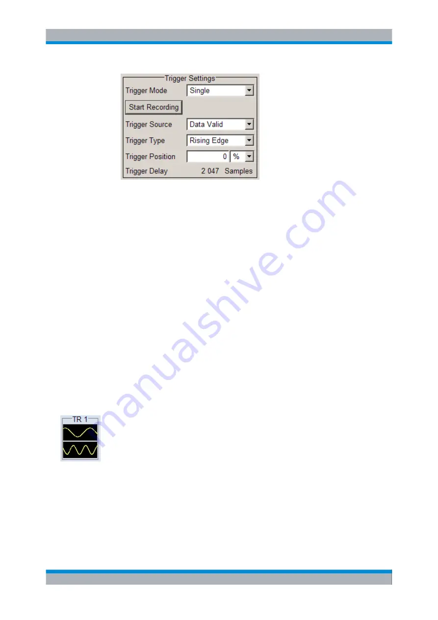
The "Status" line indicates when recording is running.
State
Activates the selected transient recorder.
Note:
Note that the R&S
EX-IQ-BOX must be switched on for data recording.
After activation, the diagram selected with
Display Type
is displayed in the "Graphics"
window.
Data Source
Selects the signal source of the I/Q data for recording.
Either signals directly fed in at the digital interfaces of the R&S
EX-IQ-BOX, or signals
generated from the waveform output memory can be recorded.
"DIG IQ IN 1"
Selects the signal fed in at the corresponding digital interface DIG I/Q
IN/OUT 1.
"DIG IQ OUT 2" Selects the signal assigned at the corresponding digital interface DIG
I/Q IN/OUT 2 output.
"ARB 1 ... 4"
Records a signal played back from one of the waveform memories.
"USER INTERFACE"
Records the signal transmitted at the USER INTERFACE.
"Sine Testsignal"
Records the internally generated sine test signal.
Smart Graphic
Activates the display of a smart graphic.
Additionally to the graphics window in the dialog, R&S
DigIConf shows the graphic in a
smaller scale, i.e. as a
Smart graphic
in the main application window, directly below the
corresponding "EX-IQ-BOX" block. It serves basic checks.
Note:
Double click the smart graphic to open the transient recorder configuration dialog.
Display Type
Select the graphical signal display. Available diagram types to display the recorded data
are
I/Q, Vector
,
CCDF
and
Power Spectrum
diagrams. The individual diagram types
are described in
chapter 6.1.6.6, "Graphical Signal Displays "
R&S DigIConf Configuration Software
Содержание EX-IQ-BOX
Страница 147: ...Protocol Settings R S EX IQ BOX 132 User Manual 1409 5570 32 05 CPRI...
Страница 391: ......


