5. E-axis assembly
64
Original Prusa i3 MK3S+ kit assembly
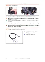
STEP 20
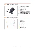
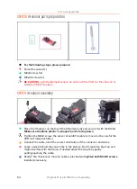
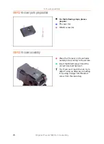
IR-sensor parts preparation
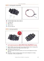
For the following steps, please prepare:
Prusa IR-sensor (1x)
M2x8 screw (1x)
M3x40 screw (1x)
BE CAREFUL
with the filament sensor, do not touch the PCB nor the chips on it.
Hold the PCB from sides.
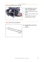
STEP 21
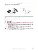
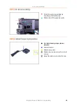
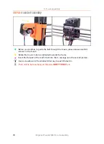
IR-sensor assembly
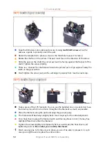
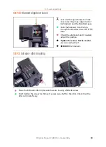
Place the IR-sensor on the top of the Extruder-body and secure it with the M2x8.
Make sure the black plastic "u-shaped" part is facing down
.
Tighten the M2x8 screw, the sensor shouldn't be able to move, but be careful the
PCB isn't indestructible ;)
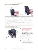
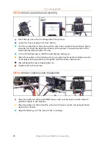
Connect the cable, mind the correct orientation of the connector and wires.
Leave a slack behind the sensor like in the picture. Don't create too big loop as it
might interfere with the frame. If needed adjust the length by gently
pulling/pushing the cable.
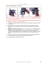
Ready? Ok, check once more no cable is pinched and
tighten both M3x10 screws
installed previously.
Содержание i3 MK3S+
Страница 6: ...6 ...
Страница 7: ...Original Prusa i3 MK3S kit assembly 7 1 Introduction ...
Страница 15: ...Original Prusa i3 MK3S kit assembly 15 2 Y axis assembly ...
Страница 36: ...36 Original Prusa i3 MK3S kit assembly 3 X axis assembly ...
Страница 44: ...44 Original Prusa i3 MK3S kit assembly 4 Z axis assembly ...
Страница 51: ...Original Prusa i3 MK3S kit assembly 51 5 E axis assembly ...
Страница 88: ...88 Original Prusa i3 MK3S kit assembly 6 LCD assembly ...
Страница 94: ...94 Original Prusa i3 MK3S kit assembly 7 Heatbed PSU assembly ...
Страница 108: ...108 Original Prusa i3 MK3S kit assembly 8 Electronics assembly ...
Страница 132: ...132 Original Prusa i3 MK3S kit assembly 9 Preflight check ...
Страница 137: ...137 Notes ...
Страница 138: ...138 ...
Страница 139: ...139 Notes ...
Страница 140: ...140 ...
Страница 141: ...141 Notes ...
Страница 142: ...142 ...
Страница 143: ...143 Notes ...
Страница 144: ...144 ...

