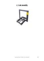
2. Y-axis assembly
Original Prusa i3 MK3S+ kit assembly
21
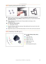
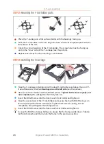
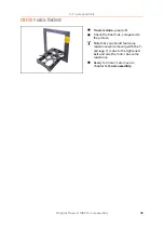
STEP 11
Mounting antivibration feet (optional)
Note this step is optional for now.
We recommend mounting the feet now to
protect the surface on your table
(workbench). However, you need to lift the frame
up before each turn.
There will be extra step at the end of the assembly to remind you of the
antivibration feet.
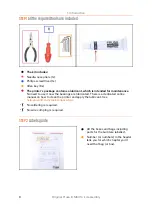
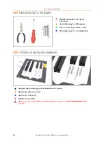
For this step, please prepare:
Antivibration foot (4x)
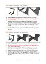
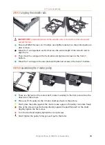
Turn the YZ frame on the side and insert the antivibration foot. Insert and turn 90
degrees to lock it in place.
Repeat this process on all 4 feet. Place them 2-3 cm from the end of each extrusion.
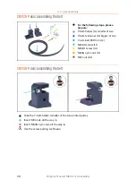
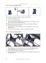
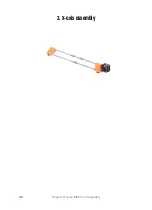
STEP 12
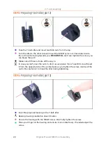
Preparing Y-belt-idler (part 1)
For the following steps, please
prepare:
Y-belt-idler (1x)
M3x18 screw (1x)
M3x10 screw (2x)
M3nN nyloc nut (1x)
M3n nut (2x)
623h bearing housing (1x)
Содержание i3 MK3S+
Страница 6: ...6 ...
Страница 7: ...Original Prusa i3 MK3S kit assembly 7 1 Introduction ...
Страница 15: ...Original Prusa i3 MK3S kit assembly 15 2 Y axis assembly ...
Страница 36: ...36 Original Prusa i3 MK3S kit assembly 3 X axis assembly ...
Страница 44: ...44 Original Prusa i3 MK3S kit assembly 4 Z axis assembly ...
Страница 51: ...Original Prusa i3 MK3S kit assembly 51 5 E axis assembly ...
Страница 88: ...88 Original Prusa i3 MK3S kit assembly 6 LCD assembly ...
Страница 94: ...94 Original Prusa i3 MK3S kit assembly 7 Heatbed PSU assembly ...
Страница 108: ...108 Original Prusa i3 MK3S kit assembly 8 Electronics assembly ...
Страница 132: ...132 Original Prusa i3 MK3S kit assembly 9 Preflight check ...
Страница 137: ...137 Notes ...
Страница 138: ...138 ...
Страница 139: ...139 Notes ...
Страница 140: ...140 ...
Страница 141: ...141 Notes ...
Страница 142: ...142 ...
Страница 143: ...143 Notes ...
Страница 144: ...144 ...

