Tape deck
GB 116
VR120
10.
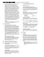
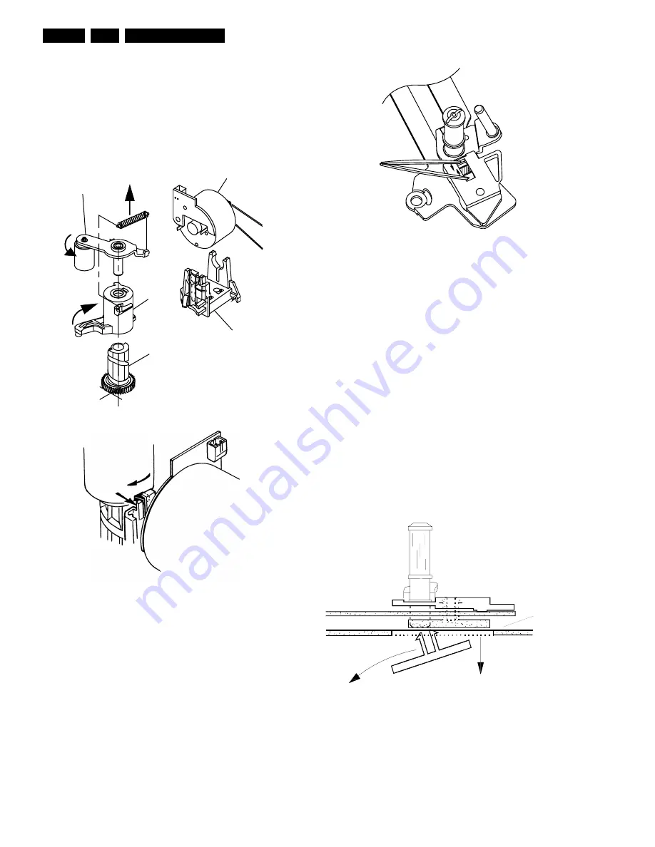
10.1.8 Pressure roller (Pos. 37)
Remove the tape deck.
Unhook and remove the pressure roller tension spring.
Release the pressure roller guide (pos. 41) from the guide in
the threading motor holder by pressing the top of the motor
guide rearwards and rotating the pressure roller guide
assembly clockwise by approximately a quarter of a turn (
see figure 10-7 ). The pressure roller and guide can now be
lifted clear.
Figure 10-7
Ensure that no grease from the pressure roller guide gets to
the capstan or pressure roller.
The reassembly is carried out in reverse order.
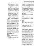
10.1.9 Roller unit right (Pos. 26)
Remove the tape deck.
Compress the two snap hooks by means of a pair of tweezers
and remove the roller assy from the roller unit right ( see
figure 10-8 ).
Unhinge the loading arm right fromthe holding plate and push
the latter towards the front of the deck to remove from the
guide (right).
NOTE:
During reassembly ensure the link from 25 is engaged in the
hole of the holder plate 26.
After replacing the roller unit (right), the tape path has to be
checked, and adjusted if necessary.
Figure 10-8
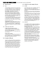
10.1.10 Roller unit left (Pos.23)
Set the drive assy to „Eject“ position.
Unhook the tension arm spring (pos. 11), to avoid the tension
arm spring being pre-loaded.
At the bottom side of the drive assy remove the tension lever
(pos.112).
Compress the two snap hooks by means of a pair of tweezers
and remove the roller assy (A) from the plate (B).
Unhinge the loading arm (left) from the holding plate and
remove the latter downward from the drive assy through the
recess in the chassis ( see figure 10-9 ).
The reassembly is carried out in reverse order.
NOTE :
During reassembly
1.
Place the carriage holding plate in the assembly with the
half-round cutout nearest the rear of the deck.
2.
When the loading arm is refitted ensure the pin on the
underside of 23 is through the link of 24B.
After replacing the roller unit (left) the tape path has to be
checked ( see division 10.2.1 Tape path), and adjusted if
necessary.
Figure 10-9
37
38
40
41
46
pair of
tweezers
A
B
Содержание VR570
Страница 12: ...Direction for use GB 12 VR120 3 3 Direction for use RT111 RT116 RT112 RT114 RT123 RT121 RT128 ...
Страница 15: ...Direction for use GB 15 VR120 3 SAT VR870L VR870CC VR720 Set width 435 mm ...
Страница 56: ...Service modes Repair tips GB 56 VR120 5 Engineer s remarks ...
Страница 60: ...60 VR120 6 Block diagrams Waveforms 6 4 Supply voltages and Bus diagram 1941 SAT MOUSE o M63100BFP ...
Страница 79: ...Circuit diagrams and PWB layouts Wiring diagram 79 VR120 7 7 16 Wiring Diagram Motherboard ...
Страница 80: ...80 VR120 7 Circuit diagrams and PWB layouts Wiring diagram 7 17 Mother board solder side 7172 CLOCK ADJUST ...
Страница 81: ...Circuit diagrams and PWB layouts Wiring diagram 81 VR120 7 Engineer s remarks ...
Страница 82: ...82 VR120 7 Circuit diagrams and PWB layouts Wiring diagram Engineer s remarks ...
Страница 83: ...Circuit diagrams and PWB layouts Wiring diagram 83 VR120 7 7 18 Mother board component side ...
Страница 119: ...Tape deck GB 119 VR120 10 ...
Страница 123: ...Tape deck GB 123 VR120 10 Engineer s remarks ...

