Circuit descriptions and List of abbreviations
GB 112
VR120
9.
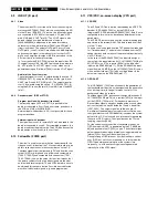
Signal
Description
Application
MTA_CROT
Audio mute / Colour rotation on/off
AIO1
AL
VS
OFP
Frame pulse
AIO1
VPO
PBH
PB-switch
VS
PG_FG
Head wheel position/-speed
AIO1
DE
PGIN
Scanner-Motor-Pulse
DE
PSS
PAL or secam-L
AIO1
FV
RECP
Record protection
AIO1
RED/C
Red signal between scart 1/2
IO
RMHI
REC-Mute/HeadPuls-Audio
AIO1
AF
SATCO
Satelite control signal
AIO1
SB1
Secam band 1
AIO1
FV
SCL
IIC bus clock
AIO1 AIO2 DE AF
FM FV
VS VPO IO
SDA
IIC bus data
AIO1 AIO2 DE AF
FM FV
VS VPO IO
SDA-VS
IIC bus data filtered to VS
VS
SFS
Sound filter switch
AIO1
FV
SH1
Standard play-Head-1
VS
SH1’
Standard play-Head-1’
VS
SH2
Standard play-Head-2
VS
SH2’
Standard play-Head-2’
VS
SIF2
Sound-interfrequency
FM FV
STBY
Stand by switch
PS AIO1 AIO2 DE
SYNC
Control track pulse
AIO1
DE
TAE
Tape end detection
AIO1
TAS
Tape start detection
AIO1
THIO
Threading motor in/out
AIO1
DE
TMO
Threading motor on/off
AIO1
DE
TRIA-ALM
Tracking audio / audio level indication
AIO1
AF
TRIV
Tracking information video
AIO1
VS
VBS
Video input
VS
IO
VFV
Video from frontend
FV
VS
IO
FOME
VIN1
Video input scart 1
IO
FOME
VISS
Control sync pulse inversion
AIO1
DE
VMOD
Video to the modulator
FV
IO
VOUT
Video from OSD part
VPO IO
VREC
Video record from I/O
VS VPO
VSB
Video from signal electronics
VS VPO
W_R
Control track write/read
AIO1
DE
WTL
Wind tacho left
DE
WTLD
Wind tacho left digital
AIO1
DE
WTR
Wind tacho right
DE
WTRD
Wind tacho right digital
AIO1
DE
AF
Audio FM Processing
page 73
AL
Audio Linear
page 72
AIO1
Central Control
page 66
AIO2
Display Control
page 65
DE
Deck Electronics
page 67
FM
Audio Stereo Nicam
page 70
FV
Frontend
page 69
FOME
Follow me
page 78
IO
In/Out
page 77
PS
Power Supply
page 64
VPO
OSD, VPS/PDC
page 76
VS
Video Signal Processing
page 74
Содержание VR570
Страница 12: ...Direction for use GB 12 VR120 3 3 Direction for use RT111 RT116 RT112 RT114 RT123 RT121 RT128 ...
Страница 15: ...Direction for use GB 15 VR120 3 SAT VR870L VR870CC VR720 Set width 435 mm ...
Страница 56: ...Service modes Repair tips GB 56 VR120 5 Engineer s remarks ...
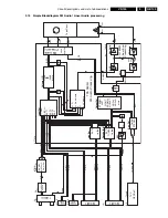
Страница 60: ...60 VR120 6 Block diagrams Waveforms 6 4 Supply voltages and Bus diagram 1941 SAT MOUSE o M63100BFP ...
Страница 79: ...Circuit diagrams and PWB layouts Wiring diagram 79 VR120 7 7 16 Wiring Diagram Motherboard ...
Страница 80: ...80 VR120 7 Circuit diagrams and PWB layouts Wiring diagram 7 17 Mother board solder side 7172 CLOCK ADJUST ...
Страница 81: ...Circuit diagrams and PWB layouts Wiring diagram 81 VR120 7 Engineer s remarks ...
Страница 82: ...82 VR120 7 Circuit diagrams and PWB layouts Wiring diagram Engineer s remarks ...
Страница 83: ...Circuit diagrams and PWB layouts Wiring diagram 83 VR120 7 7 18 Mother board component side ...
Страница 119: ...Tape deck GB 119 VR120 10 ...
Страница 123: ...Tape deck GB 123 VR120 10 Engineer s remarks ...


