Service modes, Repair tips
GB 52
VR120
5.
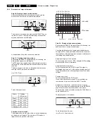
Step 10: Operation without drive - dummy mode
Before activating this mode with the SELECT key, the
recorder must be in the EJECT position.
Enter the mode by pressing the SELECT key. The motors are
then switched off and the sensors will be ignored by the deck
microprocessor. The drive can now be dismantled from the
motherboard (see dismantling instructions). Only install
drive if recorder is disconnected from mains. For signal
tracking, the recorder can be set to all drive conditions, i.e.
signal electronics, audio and IO processing are switched to
the respective operating mode.
Step 40: Option code input
If a new EEPROM is installed in the course of repairs, it must
be initialised.
By pressing the SELECT key whilst step 40 is flashing, the
decimal option A appears in the display.
By entering a 3-digit decimal code, the correct features are
set.
These codes are shown on the type-plate of the recorder.
After pressing the OK key on the remote control, the entered
code is saved. The display shows OK for approx. 3 sec. and
then the stored value in decimal format.
By pressing the UP and DOWN keys, the available options (A
to G) can be selected. The display shows the last stored
value in decimal format.
In case of an invalid entry (value >255) the activation of the
OK key causes the content of the last stored option to be
displayed and OK does not appear in the display.
Depending on the model, some bits are software or default
protected and cannot be changed by an entry. In this case,
the display shows OK, but the display returns to the default
value.
Step 98: Display Test
By pressing the SELECT key whilst step 98 is flashing, all
segments of the display are illuminated.
The step is exited by pressing SELECT again.
h n D C
are used to display the deck status
START
init switch (INIT)
END
record protection (RECP)
DEC
Loading pulses (FTA)
220-240 V ~
50Hz
MADE IN EUROPE
MADE IN EUROPE
MODEL NO:
MODEL NO:
PROD.NO:
VR120/02
VN 37
0015
123456
VN 37
123456
SHOWVIEW IS
A
TRADEMARK
APPLIED
SHOWVIEW IS
A
TRADEMARK
APPLIED
GEMST
AR
DEVELOPMENT
CORP
.
GEMST
AR
DEVELOPMENT
CORP
.
FOR
BY GEMST
AR
DEVELOPMENT
CORP
.
FOR
BY GEMST
AR
DEVELOPMENT
CORP
.
SHOWVIEW
SYSTEM
IS
MANUF
ACTURED
SHOWVIEW
SYSTEM
IS
MANUF
ACTURED
UNDER
LICENSE
FROM
UNDER
LICENSE
FROM
Range
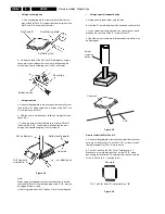
Option codes (A-G)
Evolution code
Type number
Serial number
Production date
Production center (VN),
Production code
AA
AAA BBB CCC DDD EEE FFF GGG
A13
Содержание VR570
Страница 12: ...Direction for use GB 12 VR120 3 3 Direction for use RT111 RT116 RT112 RT114 RT123 RT121 RT128 ...
Страница 15: ...Direction for use GB 15 VR120 3 SAT VR870L VR870CC VR720 Set width 435 mm ...
Страница 56: ...Service modes Repair tips GB 56 VR120 5 Engineer s remarks ...
Страница 60: ...60 VR120 6 Block diagrams Waveforms 6 4 Supply voltages and Bus diagram 1941 SAT MOUSE o M63100BFP ...
Страница 79: ...Circuit diagrams and PWB layouts Wiring diagram 79 VR120 7 7 16 Wiring Diagram Motherboard ...
Страница 80: ...80 VR120 7 Circuit diagrams and PWB layouts Wiring diagram 7 17 Mother board solder side 7172 CLOCK ADJUST ...
Страница 81: ...Circuit diagrams and PWB layouts Wiring diagram 81 VR120 7 Engineer s remarks ...
Страница 82: ...82 VR120 7 Circuit diagrams and PWB layouts Wiring diagram Engineer s remarks ...
Страница 83: ...Circuit diagrams and PWB layouts Wiring diagram 83 VR120 7 7 18 Mother board component side ...
Страница 119: ...Tape deck GB 119 VR120 10 ...
Страница 123: ...Tape deck GB 123 VR120 10 Engineer s remarks ...


