Direction for use
GB 31
VR120
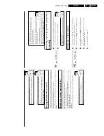
3.
The
video
recorder
is
now
ready
to
record.
The
beginning
and
end
of
the
recording
is
controlled
via
scart
socket
EXT.2
AV
2
.
When
this
function
is
switched
on,
'
x
'
will
appear
on
the
video
recorder
display.
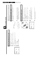
'Direct
Record'
Can
you
record
the
right
TV
channel
in
seconds
when
the
video
recorder
is
switched
off?
No
problem.
If
recording
is
started
manually,
the
switched/off
video
recorder
uses
the
current
TV
channel
setted
on
the
TV
set.
You
will
find
more
information
on
how
to
switch
'Direct
record'
on
or
off
in
the
next
section
'Direct
record'.
How
does
Direct
Record
work?
The
video
recorder
compares
the
TV
channel
selected
on
the
TV
set
with
its
stored
TV
channels
via
the
scart
cable.
If
the
same
TV
channel
is
found,
it
switches
the
video
recorder
to
the
corresponding
programme
number
and
starts
recording.
Please
do
not
change
the
TV
channel
on
the
TV
set
during
the
search
so
as
not
to
affect
the
process.
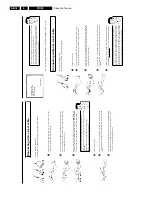
1
On
the
TV
set,
select
the
programme
number
you
want
make
the
recording
from.
2
Press
RECORD/OTR
n
with
the
video
recorder
switched
off
.
a
A
'search
symbol'
appears
in
the
display
(a
moving
symbol)
b
The
video
recorder
is
comparing
its
saved
TV
channels
with
those
of
the
TV
set.
Please
do
not
change
the
TV
channel
on
the
TV
set
as
long
as
the
'search
symbol'
(a
moving
symbol)
is
being
displayed.
a
'
NOTV
'
appears
in
the
display
b
This
TV
channel
could
not
be
found
in
the
video
recorder's
memory.
Check
that
all
TV
channels
saved
on
the
TV
set
are
available
in
the
video
recorder.
If
required,
save
any
missing
channels.
Please
read
the
section
'Manual
TV
channel
search'.
3
Stop
recording
with
STOP
h
.
5
Confirm
with
OK
.
6
To
end,
press
MENU
.
Automatic
controlled
recording
from
a
satellite
receiver
(RECORD
LINK)
This
function
automatically
starts
recording
on
the
switched-off
video
recorder
when
a
video
signal
is
recognised
through
the
connected
scart
cable.
If
your
satellite
receiver
has
a
programming
function,
the
recording
will
start
automatically
(as
long
as
the
satellite
receiver
is
switched
on).
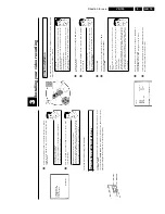
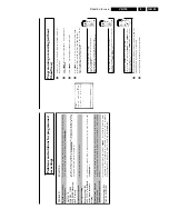
1
Switch
on
the
TV
set.
If
required,
select
the
programme
number
for
the
video
recorder.
2
Press
MENU
on
the
remote
control.
The
main
menu
will
appear.
3
Select
line
'
SPECIAL
SETTINGS
'
using
P
r=
or
;q
P
and
confirm
with
OK
.
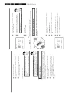
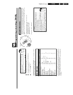
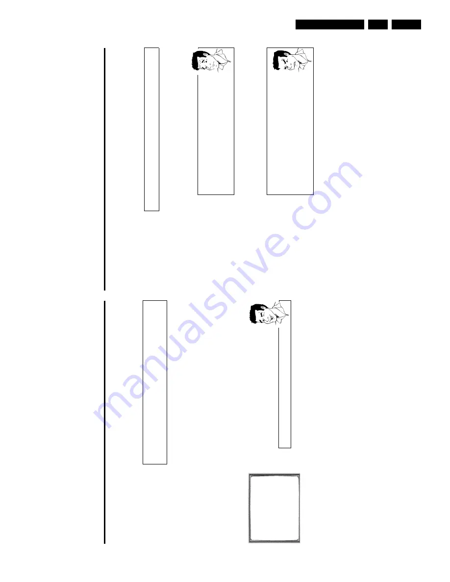
SPECIAL
SETTINGS
OSD
è
O
N
p
CLOCK
DISPLAY
OFF
REPEAT
PLAY
OFF
DIRECT
RECORD
ON
________________________________
EXITpMENU
STOREpOK
4
Select
line
'
RECORD
LINK
'
using
P
r=
or
;q
P
.
5
Select
function
'
ON
'
with
Q
or
P
.
Switching
off
'Record
Link'
To
switch
off
the
function,
select
'
OFF
'.
6
Confirm
with
OK
.
7
To
end,
press
MENU
.
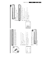
8
Insert
a
cassette.
9
Use
a
scart
cable
to
connect
scart
socket
EXT.2
AV
2
on
the
video
recorder
to
the
corresponding
scart
socket
on
the
satellite
receiver.
0
Programme
the
satellite
receiver
with
the
required
information
(programme
number
of
the
TV
channel,
start
time,
end
time).
If
necessary,
please
see
the
operating
instructions
for
your
satellite
receiver.
A
Switch
off
the
video
recorder
with
STANDBY/ON
m
.
Содержание VR570
Страница 12: ...Direction for use GB 12 VR120 3 3 Direction for use RT111 RT116 RT112 RT114 RT123 RT121 RT128 ...
Страница 15: ...Direction for use GB 15 VR120 3 SAT VR870L VR870CC VR720 Set width 435 mm ...
Страница 56: ...Service modes Repair tips GB 56 VR120 5 Engineer s remarks ...
Страница 60: ...60 VR120 6 Block diagrams Waveforms 6 4 Supply voltages and Bus diagram 1941 SAT MOUSE o M63100BFP ...
Страница 79: ...Circuit diagrams and PWB layouts Wiring diagram 79 VR120 7 7 16 Wiring Diagram Motherboard ...
Страница 80: ...80 VR120 7 Circuit diagrams and PWB layouts Wiring diagram 7 17 Mother board solder side 7172 CLOCK ADJUST ...
Страница 81: ...Circuit diagrams and PWB layouts Wiring diagram 81 VR120 7 Engineer s remarks ...
Страница 82: ...82 VR120 7 Circuit diagrams and PWB layouts Wiring diagram Engineer s remarks ...
Страница 83: ...Circuit diagrams and PWB layouts Wiring diagram 83 VR120 7 7 18 Mother board component side ...
Страница 119: ...Tape deck GB 119 VR120 10 ...
Страница 123: ...Tape deck GB 123 VR120 10 Engineer s remarks ...


