Dismantling instructions
GB 46
VR120
4.
4.
Dismantling instructions
4.1
Dismantling instructions
General guidelines for dismantling housing components,
electronic parts and the drive mechanism
Always disconnect from mains before dismantling or
assembly.
Due to the supply voltages (hot circuit) on the primary side of
the switched-mode power supply, an isolating transformer is
required for the operation of the device.
The drive or the drive/motherboard unit must not be pulled
out by the cross struts!
Components placed below the tape deck has to be inserted
exactly.
The use of a regulating isolating transformer is
recommended for detecting faults around the power supply.
All screws of the video recorder can be removed or tightened
with a 10* torx screwdriver .
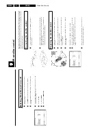
1. Housing cover (Figure 4-1)
–
Remove the four screws (A).
–
Push catch (S) inwards, lifting lid at the same time to
move out of groove.
–
Slide housing cover back by approx. 1 cm.
–
Push centre of housing cover sides on underside approx.
1 cm outwards and lift up the housing cover.
Assembly
Assemble in reverse order.
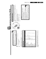
2. Base plate (Figure 4-2)
The base plate may not be removed from the frame!
3. Front panel (Figure 4-2)
Preparation
Dismantle the housing lid as described in section 1.
–
Position the device with the base plate facing upwards.
–
Undo the six catches (S) one after the other, starting from
the left or the right.
–
Remove the front panel by pulling it forwards.
–
For devices with shuttle print or socket print, disconnect
the cabling to the motherboard.
Assembly
Assemble in reverse order (device in operational position).
Important
–
The lift flap lever should be connected to the lift flap
guide.
–
Check that all catches are engaged.
Figure 4-1
Figure 4-2
S
A
A
A
A
S
A
A
A
A
S
S
S
S
S
S
S
S
S
S
S
S
S
S
S
S
S
S
S
S
S
S
S
S
S
S
S
S
S
S
S
S
for VR720, VR870x, 435 mm sets
Содержание VR570
Страница 12: ...Direction for use GB 12 VR120 3 3 Direction for use RT111 RT116 RT112 RT114 RT123 RT121 RT128 ...
Страница 15: ...Direction for use GB 15 VR120 3 SAT VR870L VR870CC VR720 Set width 435 mm ...
Страница 56: ...Service modes Repair tips GB 56 VR120 5 Engineer s remarks ...
Страница 60: ...60 VR120 6 Block diagrams Waveforms 6 4 Supply voltages and Bus diagram 1941 SAT MOUSE o M63100BFP ...
Страница 79: ...Circuit diagrams and PWB layouts Wiring diagram 79 VR120 7 7 16 Wiring Diagram Motherboard ...
Страница 80: ...80 VR120 7 Circuit diagrams and PWB layouts Wiring diagram 7 17 Mother board solder side 7172 CLOCK ADJUST ...
Страница 81: ...Circuit diagrams and PWB layouts Wiring diagram 81 VR120 7 Engineer s remarks ...
Страница 82: ...82 VR120 7 Circuit diagrams and PWB layouts Wiring diagram Engineer s remarks ...
Страница 83: ...Circuit diagrams and PWB layouts Wiring diagram 83 VR120 7 7 18 Mother board component side ...
Страница 119: ...Tape deck GB 119 VR120 10 ...
Страница 123: ...Tape deck GB 123 VR120 10 Engineer s remarks ...

