90
VR120
7.
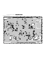
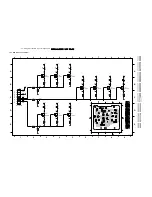
Circuit diagrams and PWB layouts, Wiring diagram
7.32 Test point overview
9763
9713
ZF-out
1704
5704
BAND I
ADJ.
40.4 MHz
ADJ.
3730
5702
AFC
ADJ.
9719
3707
AGC
ADJ.
1955
STV6401
7904
1
15
14
28
7072
LA7339A
3089
3088
SEC-CHROMA
CURRENT
3.3 MHz
ADJ.
1801
REC.
PROT
9034
CSRP
17
3.3 MHz
9021
FMPV
DECK-
CONTROL
AIO1
TMP93CT76F
7899A-B
1
30
31
50
51
80
81
100
1982
1307
T125mA
MP13
1304
T125mA
MP13
1309
T100mA
HP1
9803
1306
T1.6A
MP160
5301
1
3
5
6
1
2
4
3
1
4
5
8
1301
G
D
S
7302
1956
1
1947
1948
1965
5600
1961
3625
+
2613
TP
BIAS
ADJ.
-
2492
MOTOR
ADJ.
9417
9869
DRUM
5VS1
MOT1
1
1911, 1912
DUMMY for
2 head sets
LA71595M
7004 A-C
1
30
31
50
51
80
81
100
1
11
12
22
23
33
34
44
TDA9605
7650
1
7
8
14
7530
LM339
VPO
1
20
11
10
7502
SDA5620 for VPO
SDA5650 for VPS
1802
1
42
22
21
M63100BFP
7463
7760
7761
44
1
33
22
23
12
11
1
11
12
22
23
33
34
44
34
7761
7760
MSP3415D
TD
A9873HZ
1
1
1
12
13
24
7705
1 4
5
8
7818
M24C08
DECK-
CONTROL
(DE)
7300
TCET1101G
7303
MC44608
MAIN
CINCH
rear
9762
STEREO
(ST)
7911
1308
T1.25A
MP125
9802
SYNC
9801
TRIV
not used for M63100BFP
DISPLAY
CLOCK ADJUST
SAT-
contr.
1941
DISPLAY- CONTROL- AIO2
Содержание VR570
Страница 12: ...Direction for use GB 12 VR120 3 3 Direction for use RT111 RT116 RT112 RT114 RT123 RT121 RT128 ...
Страница 15: ...Direction for use GB 15 VR120 3 SAT VR870L VR870CC VR720 Set width 435 mm ...
Страница 56: ...Service modes Repair tips GB 56 VR120 5 Engineer s remarks ...
Страница 60: ...60 VR120 6 Block diagrams Waveforms 6 4 Supply voltages and Bus diagram 1941 SAT MOUSE o M63100BFP ...
Страница 79: ...Circuit diagrams and PWB layouts Wiring diagram 79 VR120 7 7 16 Wiring Diagram Motherboard ...
Страница 80: ...80 VR120 7 Circuit diagrams and PWB layouts Wiring diagram 7 17 Mother board solder side 7172 CLOCK ADJUST ...
Страница 81: ...Circuit diagrams and PWB layouts Wiring diagram 81 VR120 7 Engineer s remarks ...
Страница 82: ...82 VR120 7 Circuit diagrams and PWB layouts Wiring diagram Engineer s remarks ...
Страница 83: ...Circuit diagrams and PWB layouts Wiring diagram 83 VR120 7 7 18 Mother board component side ...
Страница 119: ...Tape deck GB 119 VR120 10 ...
Страница 123: ...Tape deck GB 123 VR120 10 Engineer s remarks ...


