Direction for use
GB 33
VR120
3.
J
Programming
a
recording
(TIMER)
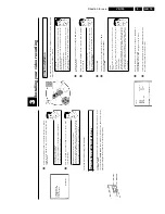
General
information
Use
programmed
recording
to
automatically
start
and
stop
a
recording
at
a
later
date.
The
video
recorder
will
switch
to
the
right
programme
number
and
begin
recording
at
the
correct
time.
With
this
video
recorder,
you
can
pre-programme
up
to
six
recordings
within
a
period
of
one
month.
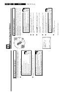
To
make
a
programmed
recording,
your
video
recorder
needs
to
know:
*
the
date
you
want
to
make
the
recording
*
the
programme
number
of
the
TV
channel
*
the
start
and
stop
time
of
the
recording
*
VPS
or
PDC
on
or
off
This
information
is
saved
in
a
'TIMER
block'.
What
is
'VPS/PDC'?
'VPS'
(Video
Programming
System)/
'PDC'
(Programme
Delivery
Control)
are
used
to
control
the
start
and
duration
of
TV
channel
recordings.
If
a
T
V
programme
starts
earlier
or
ends
later
than
was
scheduled,
the
video
recorder
will
then
turn
on
and
off
and
the
correct
time.
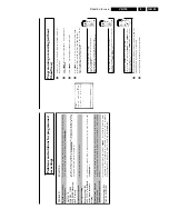
What
do
I
need
to
know
about
'VPS/PDC'?
Usually
the
start
time
is
the
same
as
the
VPS
or
PDC
time.
But
if
your
TV
guide
gives
a
VPS
or
PDC
time
which
is
different
from
the
programme's
start
time,
e.g.
'20.15
(VPS/PDC
20.14)',
you
must
enter
the
VPS/PDC
time
'20.14'
exact
to
the
minute
as
the
start
time.
If
you
want
to
programme
a
time
that
is
different
from
the
VPS
or
PDC
time,
you
must
switch
off
VPS
or
PDC.
Only
one
TV
program
of
a
T
V
channel
can
be
controlled
using
'VPS/PDC'
at
a
time.
If
you
want
to
record
two
or
more
TV
programmes
on
a
T
V
channel
using
'VPS/PDC',
you
will
need
to
programme
these
as
two
separate
recordings.
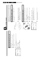
a
My
Set
Top
Box
does
not
switch
to
programme
number
12
b
Please
check
that
you
entered
the
correct
code
number.
Repeat
step
6
.
b
Also
try
other
code
numbers.
b
Please
make
sure
that
the
IR
electronic
eye
on
the
Set
Top
Box
is
not
blocked.
b
You
may
wish
to
reposition
the
SAT
mouse
(repeat
steps
1
and
6
).
8
Confirm
the
correct
code
number
with
OK
.
9
Affix
the
satellite
control
to
the
Set
Top
Box
using
the
adhesive
strip
on
the
bottom
of
the
satellite
control.
0
To
end,
press
the
MENU
button.
The
satellite
control
has
now
been
successfully
installed.
Further
information
regarding
the
use
of
the
satellite
control
for
programmed
recordings
is
included
in
chapter
'Programming
a
recording
(TIMER)'.
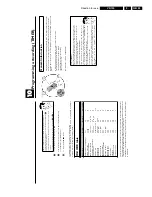
IR/CODE
table
Set
Top
Box
Provider
Country
code
number
AMSTRAD
DRX
100
Sky
Digibox
Sky
UK
3
ASTON
Xena
1500
Canal+
FR
13
CANAL+
Canalsatellite
Canal+
FR
1
ECHOSTAR
D-2500-IP
Free-to-Air
D,
FR,
UK
11
GRUNDIG
Digibox
GDS200/1
Sky
UK
3
HUMAXF1-AVCI
Free-to-Air
D,
FR,
UK
2
NOKIA
D-Box
Premiere
World
D
5
,
1
5
NOKIA
9200S
Free-to-Air
FR,
UK
6
NOKIA
9850T
On
Digital
UK
3
PACE
DTR730-IM
On
Digital
UK
12
PACE
BSKYB
2200
Sky
UK
3
PANASONIC
TU-DSB30
Sky
UK
3
PHILIPS
DTX
6371
On
Digital
UK
4
SAGEM
ISD
3100
TPS
FR
14
SAGEM
ISD
3200
TPS
FR
10
TPS
Thomson
TPS
FR
10
TPS
Sagem
TPS
FR
10
XCOM
CDTV
2000
TPS
FR
7
XCOM
CDTV
350
TPS
FR
9
The
proper
function
of
the
satellite
control
can
only
be
guaranteed
for
the
listed
combinations
of
Set
Top
Boxes
and
providers
in
the
respective
countries.
Other
combinations
could
influence
the
switching
of
the
programme
numbers
or
may
not
function
properly.
Modifications
of
the
technical
specifications
of
the
Set
Top
Boxes
can
cause
the
satellite
control
to
malfunction.
Содержание VR570
Страница 12: ...Direction for use GB 12 VR120 3 3 Direction for use RT111 RT116 RT112 RT114 RT123 RT121 RT128 ...
Страница 15: ...Direction for use GB 15 VR120 3 SAT VR870L VR870CC VR720 Set width 435 mm ...
Страница 56: ...Service modes Repair tips GB 56 VR120 5 Engineer s remarks ...
Страница 60: ...60 VR120 6 Block diagrams Waveforms 6 4 Supply voltages and Bus diagram 1941 SAT MOUSE o M63100BFP ...
Страница 79: ...Circuit diagrams and PWB layouts Wiring diagram 79 VR120 7 7 16 Wiring Diagram Motherboard ...
Страница 80: ...80 VR120 7 Circuit diagrams and PWB layouts Wiring diagram 7 17 Mother board solder side 7172 CLOCK ADJUST ...
Страница 81: ...Circuit diagrams and PWB layouts Wiring diagram 81 VR120 7 Engineer s remarks ...
Страница 82: ...82 VR120 7 Circuit diagrams and PWB layouts Wiring diagram Engineer s remarks ...
Страница 83: ...Circuit diagrams and PWB layouts Wiring diagram 83 VR120 7 7 18 Mother board component side ...
Страница 119: ...Tape deck GB 119 VR120 10 ...
Страница 123: ...Tape deck GB 123 VR120 10 Engineer s remarks ...

