Direction for use
GB 36
VR120
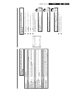
3.
Programming
a
recording
with
'TURBO
TIMER'
With
this
function,
programming
a
recording
that
takes
place
within
the
next
24
hours,
wil
lb
e
quick
and
easy.
The
following
pre-set
information
will
appear
in
the
display
when
you
program
me
a
recording
using
'TURBO
TIMER'.
Programme
number
=
the
programme
number
currently
selected
(TV
channel)
Start
time
=
current
time
End
time
=
current
time
+2
hours
BBC1
1
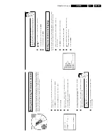
Press
TURBO
TIMER
on
the
remote
control.
The
current
set
programme
number
will
appear
in
the
display,
for
instance,
'
PROG.
01
'.
If
required,
you
can
change
this
using
;q
P
or
P
r=
.
a
'
CLK
'
will
flash
in
the
video
recorder
display
b
This
display
means
that
the
video
recorder
clock
is
not
set
correctly.
Please
read
the
section
'Setting
the
time
and
date'
in
chapter
'Installing
your
video
recorder'
Controlling
the
satellite
receiver
(IR/Sat
control)
Using
SELECT
,
you
can
change
the
input
for
a
satellite
TV
channel.
'
S---
'
will
appear
in
the
display.
Enter
the
programme
number
for
the
satellite
TV
channel
using
the
number
buttons
0-9
on
the
remote
control.
Attention:
For
this
to
work,
the
IR-Sat
control
must
be
installed
correctly
(chapter
'IR
Sat
control',
'Connecting
the
Sat
control'.
20:00
2
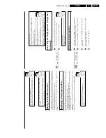
Press
TURBO
TIMER
.
The
current
time
(=
start
time)
will
appear
in
the
display,
for
instance,
'
START
20:00
'.
If
required,
you
can
change
this
using
;q
P
or
P
r=
.
22:00
3
Press
TURBO
TIMER
.
The
end
time
will
appear
in
the
display,
for
instance,
'
END
22:00
'.
'
END
22:00
'.
If
required,
you
can
change
this
using
;q
P
or
P
r=
.
4
Press
TURBO
TIMER
.
'
OK
'
will
briefly
appear
in
the
video
recorder
display.
Programming
is
now
complete.
5
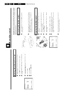
Insert
a
cassette
with
an
intact
security
tab
(unprotected).
Using
'Tape
List'
To
save
a
recording
in
the
'Tape
List'
or
to
use
a
'Tape
List'
cassette,
enter
the
cassette
number
using
the
number
buttons
0-9
on
the
remote
control.
The
cassette
is
being
checked.
You
can
find
more
information
on
the
'Tape
List'
in
the
chapter
'Tape
List'.
7
Switch
off
with
STANDBY/ON
m
.
The
programmed
recording
will
only
function
when
the
video
recorder
is
switched
off
with
STANDBY/ON
m
.
If
any
of
the
TIMER
blocks
are
in
use,
'
k
'
will
light
up
on
the
video
recorder
display.
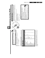
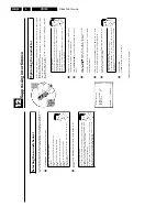
Problem
solving
for
programmed
recordings
PROBLEM
SOLUTION
The
video
recorder
does
not
react
b
While
a
programmed
recording
is
being
made,
you
cannot
operate
your
video
recorder
manuall
y.
If
you
want
to
cancel
the
programmed
recording,
press
STANDBY/ON
m
.
'
SWITCH
TO
STANDBY-
TIMER
RECORDING
'
flashes
on
the
TV
screen
b
The
video
recorder
was
switched
on
several
minutes
before
the
start
of
a
programmed
recordin
g.
Switch
off
the
video
recorder
with
STANDBY/ON
m
.
A
programmed
recording
(timer)
w
ill
only
function
if
the
video
recorder
is
switched
off.
A
cassette
was
automatically
ejected
during
recording
b
The
end
of
the
tape
was
reached
during
recording.
Error
message:
'
NO
CASSETTE
''
k
'
will
flash
in
the
video
recorder
display
b
No
cassette
was
inserted.
Insert
a
cassette
and
switch
off
the
video
recorder
usin
g
STANDBY/ON
m
.
The
'
PROTECTED
CASSETTE
'
error
message
appears
briefly
on
the
screen
then
the
cassette
is
ejected.
b
A
cassette
was
inserted
with
the
security
tab
removed.
Undo
the
erase
protection
(chapte
r
'Manual
Recording',
section
'Preventing
accidental
erasing
of
cassettes')
or
insert
a
differen
t
cassette.
Error
message:
'
ALL
TIMERS
OCCUPIED
'
b
If
this
error
message
appears
after
pressing
TIMER
k
,
then
all
TIMER
blocks
are
alread
y
programmed.
No
more
recordings
can
be
programmed.
If
you
want
to
clear
or
check
a
programmed
recording
(TIMER
block),
select
it
with
;q
P
or
P
r=
.
The
'
DATA
ERROR
'
message
appears
on
the
screen.
b
The
data
for
the
recording
could
not
be
transferred.
Please
check
date,
start
time
and
end
tim
e
of
the
programmed
recording.
Содержание VR570
Страница 12: ...Direction for use GB 12 VR120 3 3 Direction for use RT111 RT116 RT112 RT114 RT123 RT121 RT128 ...
Страница 15: ...Direction for use GB 15 VR120 3 SAT VR870L VR870CC VR720 Set width 435 mm ...
Страница 56: ...Service modes Repair tips GB 56 VR120 5 Engineer s remarks ...
Страница 60: ...60 VR120 6 Block diagrams Waveforms 6 4 Supply voltages and Bus diagram 1941 SAT MOUSE o M63100BFP ...
Страница 79: ...Circuit diagrams and PWB layouts Wiring diagram 79 VR120 7 7 16 Wiring Diagram Motherboard ...
Страница 80: ...80 VR120 7 Circuit diagrams and PWB layouts Wiring diagram 7 17 Mother board solder side 7172 CLOCK ADJUST ...
Страница 81: ...Circuit diagrams and PWB layouts Wiring diagram 81 VR120 7 Engineer s remarks ...
Страница 82: ...82 VR120 7 Circuit diagrams and PWB layouts Wiring diagram Engineer s remarks ...
Страница 83: ...Circuit diagrams and PWB layouts Wiring diagram 83 VR120 7 7 18 Mother board component side ...
Страница 119: ...Tape deck GB 119 VR120 10 ...
Страница 123: ...Tape deck GB 123 VR120 10 Engineer s remarks ...


