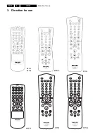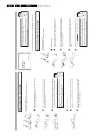
Direction for use
GB 24
VR120
3.
D
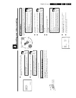
Important
notes
for
operation
Switching
on
You
can
switch
on
the
video
recorder
with
the
STANDBY/ON
m
button,
the
number
button
s
0-9
or
by
putting
in
a
cassette.
Automatic
switch/off
If
the
video
recorder
is
not
used
for
several
minutes,
it
switches
itself
off
automatically.
Th
is
function
can
be
deactivated
(e.g.
if
you
want
to
use
the
video
recorder
as
a
T
V
receiver).
For
mor
e
information,
please
read
the
section
'Automatic
switch-off'
in
chapter
'Additional
functions'.
Time
in
the
display
If
you
have
switched
the
video
recorder
off
with
STANDBY/ON
m
,
the
time
will
show
in
th
e
display,
e.g.
'18:00'.
If
the
clock
has
not
been
set,
'
--:--
'
will
appear.
When
the
video
recorder
is
switched
off
and
the
time
isn't
shown
in
the
video
recorder
displa
y,
the
clock
display
may
be
switched
off.
You
will
find
more
information
in
the
chapter
'Addition
al
functions'
section
'Switch
off
the
clock
display'.
Energy
consumption
The
video
recorder
should
always
be
connected
to
the
mains
so
as
not
to
affect
the
use
of
the
T
V
or
programmed
recordings.
Your
video
recorder
uses
less
than
4W
(with
clock
display
switched
off).
Power
outage/no
power
Channel
information
remains
saved
for
up
to
1
year,
the
time
and
timer
information
is
saved
for
u
p
to
3
hours.
Emergency
exit
The
video
recorder
and
the
remote
control
have
the
option
of
an
'Emergency
exit'.
You
can
us
e
the
STANDBY/ON
m
button
to
interrupt
any
function
or
step
during
use.
You
can
operate
your
device
without
worry.
There
is
no
risk
whatsoever
of
damaging
the
vide
o
recorder
by
performing
user
steps
incorrectly.
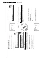
Navigation
in
the
screen
menu
You
can
check/change
many
functions
and
settings
of
your
video
recorder
via
the
screen
m
enu.
The
individual
functions
are
selected
as
follows:
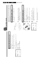
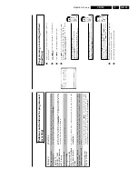
MENU
CLOCK
AUTO
TUNING
MANUAL
SEARCH
FOLLOW
TV
TV
CHANNEL
ALLOC.
RECORD
SPEED
AUTO
STANDBY
VIDEOSYSTEM
LANGUAGE
SPECIAL
SETTINGS
________________________________
…EXITpMENU
OK
†HOTLINEpCL
Call
up
the
menu:
with
MENU
.
To
select:
with
P
r=
or
;q
P
.
To
enter
or
change
your
selection:
with
the
number
buttons
0-9
or
with
Q
or
P
.
To
save
or
confirm:
with
OK
.
To
cancel:
with
STANDBY/ON
m
.
To
end:
with
MENU
.
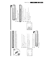
Setting
the
time
and
date
If
the
display
shows
an
incorrect
time
or
'
--:--
',
the
time
and
date
must
be
reset
manually.
If
a
T
V
channel
which
transmits
TXT/PDC
(teletext/PDC)
is
stored
under
programme
num
ber
'P01',
time/date
will
automatically
be
taken
from
the
TXT/PDC
information.
(SMART
CLOCK
)
1
Switch
on
the
TV
set.
If
required,
select
the
programme
number
for
the
video
recorder.
2
Press
MENU
on
the
remote
control.
The
main
menu
will
appear.
3
Select
line
'
CLOCK
'
using
P
r=
or
;q
P
and
confirm
with
OK
.
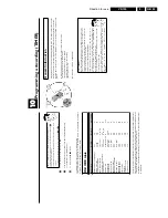
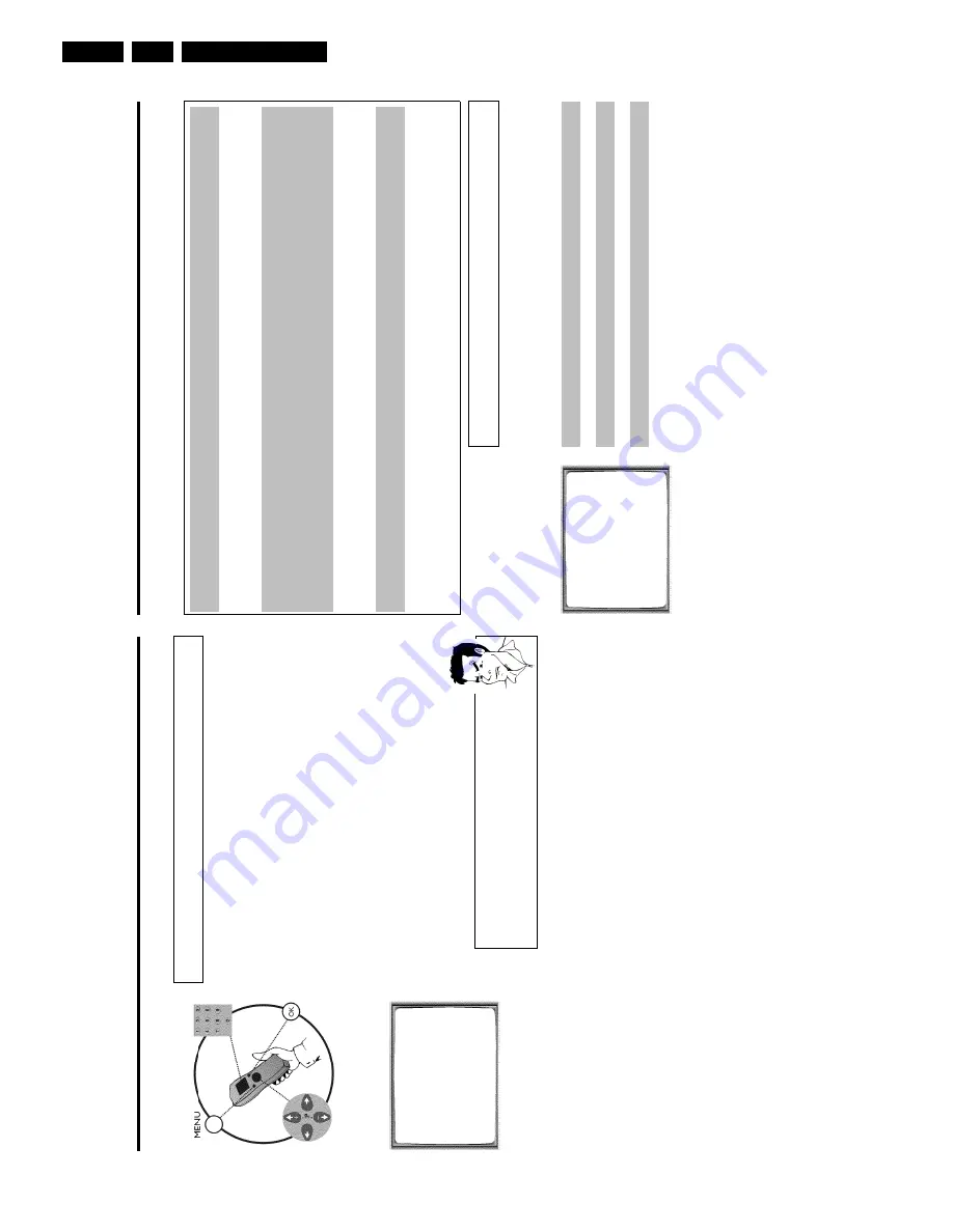
CLOCK
YEAR
è
2001
p
MONTH
01
DATE
01
TIME
20:00
SMART
CLOCK
ON
________________________________
EXITpMENU
STOREpOK
4
Check
the
year
in
line
'
YEAR
'.
If
required,
please
change
the
year
with
the
number
buttons
0-9
on
the
remote
control.
5
Select
the
next
line
with
;q
P
or
P
r=
.
6
Check
'
MONTH
',
'
DATE
'
and
'
TIME
'
in
the
same
way.
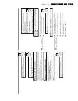
a
Time/date
is
displayed
incorrectly
despite
manual
setting
b
With
Smart
Clock,
time/date
is
transferred
from
the
TV
channel
saved
on
'P01'
and
automatically
corrected.
Switch
off
Smart
Clock.
In
line
'
SMART
CLOCK
',
select
'
OFF
'
using
Q
or
P
.
You
can
switch
on
'SMART
CLOCK'
again
when
you
select
'
ON
'.
7
Check
the
displayed
settings
and
confirm
with
OK
.
'
STORED
'
will
appear
briefly
on
the
screen.
8
To
end,
press
MENU
.
Содержание VR570
Страница 12: ...Direction for use GB 12 VR120 3 3 Direction for use RT111 RT116 RT112 RT114 RT123 RT121 RT128 ...
Страница 15: ...Direction for use GB 15 VR120 3 SAT VR870L VR870CC VR720 Set width 435 mm ...
Страница 56: ...Service modes Repair tips GB 56 VR120 5 Engineer s remarks ...
Страница 60: ...60 VR120 6 Block diagrams Waveforms 6 4 Supply voltages and Bus diagram 1941 SAT MOUSE o M63100BFP ...
Страница 79: ...Circuit diagrams and PWB layouts Wiring diagram 79 VR120 7 7 16 Wiring Diagram Motherboard ...
Страница 80: ...80 VR120 7 Circuit diagrams and PWB layouts Wiring diagram 7 17 Mother board solder side 7172 CLOCK ADJUST ...
Страница 81: ...Circuit diagrams and PWB layouts Wiring diagram 81 VR120 7 Engineer s remarks ...
Страница 82: ...82 VR120 7 Circuit diagrams and PWB layouts Wiring diagram Engineer s remarks ...
Страница 83: ...Circuit diagrams and PWB layouts Wiring diagram 83 VR120 7 7 18 Mother board component side ...
Страница 119: ...Tape deck GB 119 VR120 10 ...
Страница 123: ...Tape deck GB 123 VR120 10 Engineer s remarks ...

