78
VR120
7.
Circuit diagrams and PWB layouts, Wiring diagram
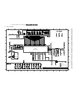
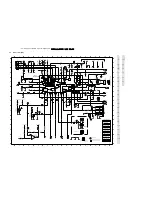
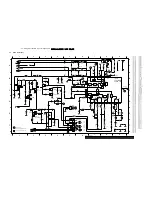
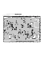
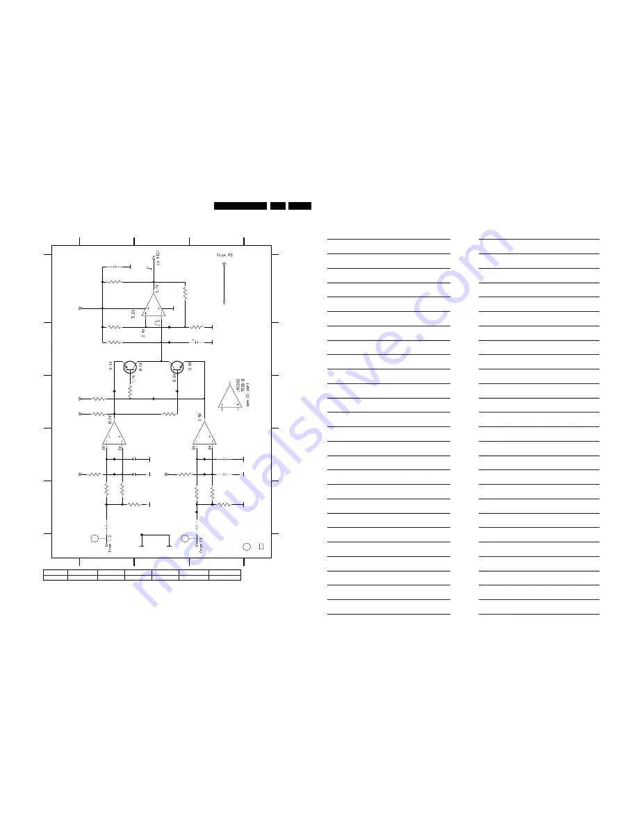
7.15 FOLLOW ME Part (FOME)
E
2530 A1
2537 E3
2536 E1
3543 E3
I531 D1
I532 D1
E
3544 E3
2535 D3
3530 A1
I536 B2
I537 A2
I541 E3
I540 D3
7530-A A2
3531 A2
for FOME or <1W only
1
C
3540 D2
3532 B1
I535 C2
3546 E3
7532 B2
7530-C D1
2531 B3
2533 D3
2534 D1
7530-D D3
3534 B1
3537 C1
6
B
3536 C1
D
C530 E2
I534 C2
I530 E1
3541 E1
3535 C1
A
7531 B1
C
OSCILLOGRAMS
I533 C1
..V MEASURED IN RECORD MODE
3542 E1
30
..V MEASURED IN PLAYBACK MODE
B
I539 D3
22K
3532
..
3539 D1
3545 E2
D
3
1
2532 D1
2
3
3538 C2
F530 E2
3533 B3
2
A
GNDFOME
C530
GNDVIO
2K2
3536
180p
2535
3542
33K
5V_1WSTBY
4K7
3534
100K
3531
33K
3543
15K
3533
13
LM339D
7530-A
5
4
2
3
12
LM339D
7530-D
11
10
BC847BW
7532
5V_1WSTBY
7531
BC847BW
10u
2531
I535
I536
I537
33K
3545
4K7
3535
I540
3541
33K
3530
4K7
F530
3539
10M
2536
1u
2534
180p
2n2
2533
5V_1WSTBY
3546
33K
LM339D
7530-C
9
8
14
5V_1WSTBY
100n
2530
I539
5V_1WSTBY
10M
3540
1u
2537
2K2
3537
5V_1WSTBY
2532
2n2
I534
I533
I531
33K
3544
I541
I532
3538
4K7
I530
VFV
VIN1
FOME
5V_1WSTBY
FoMe-8920-9
Interconnections:
AF page 73
AL page 72
AIO1 page 66 AIO2 page 65 DE page 67
FM ST page 70 FM NIC-page 71
FV page 69
FOME page 78 I/O page 77
PS page 64
VPO page 76 VS page 75
VS_S page 74
Engineer's remarks:
Содержание VR570
Страница 12: ...Direction for use GB 12 VR120 3 3 Direction for use RT111 RT116 RT112 RT114 RT123 RT121 RT128 ...
Страница 15: ...Direction for use GB 15 VR120 3 SAT VR870L VR870CC VR720 Set width 435 mm ...
Страница 56: ...Service modes Repair tips GB 56 VR120 5 Engineer s remarks ...
Страница 60: ...60 VR120 6 Block diagrams Waveforms 6 4 Supply voltages and Bus diagram 1941 SAT MOUSE o M63100BFP ...
Страница 79: ...Circuit diagrams and PWB layouts Wiring diagram 79 VR120 7 7 16 Wiring Diagram Motherboard ...
Страница 80: ...80 VR120 7 Circuit diagrams and PWB layouts Wiring diagram 7 17 Mother board solder side 7172 CLOCK ADJUST ...
Страница 81: ...Circuit diagrams and PWB layouts Wiring diagram 81 VR120 7 Engineer s remarks ...
Страница 82: ...82 VR120 7 Circuit diagrams and PWB layouts Wiring diagram Engineer s remarks ...
Страница 83: ...Circuit diagrams and PWB layouts Wiring diagram 83 VR120 7 7 18 Mother board component side ...
Страница 119: ...Tape deck GB 119 VR120 10 ...
Страница 123: ...Tape deck GB 123 VR120 10 Engineer s remarks ...


