Direction for use
GB 41
VR120
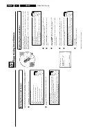
3.
Using
your
video
recorder
remote
control
with
your
TV
set
With
the
enclosed
multicode
remote
control
you
can
control
the
main
functions
of
your
TV
set.
To
do
this,
you
must
first
enter
a
code
number
that
corresponds
to
the
make
of
your
TV
set.
You
will
find
a
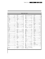
summary
of
all
available
remote
control
commands
on
the
last
page
of
this
manual.
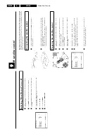
1
Hold
down
the
Sr
button.
2
Using
the
number
buttons
0-9
,
enter
the
code
number
that
corresponds
to
the
make
(manufacturer)
of
your
TV
set.
When
you
have
entered
the
code
number
correctly,
the
TV
set
will
switch
off.
a
My
TV
set
will
not
switch
off.
b
Also
try
to
enter
code
numbers
of
other
manufacturers.
b
In
some
cases,
it
is
possible
that
your
TV
set
will
not
react
to
the
selected
code
numbers.
If
this
is
the
case,
you
unfortunately
cannot
use
this
function.
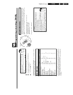
By
using
the
TV
buttons
on
the
panel
in
the
middle
of
the
control,
you
can::
qS
increase
the
TV
volume
Sr
decrease
the
TV
volume
q
TV
next
programme
number
TV
r
previous
programme
number
To
switch
off
the
TV
(
TV
m
),
press
Sr
and
TV
r
at
the
same
time.
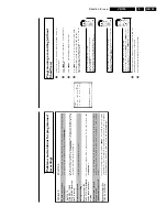
Automatic
switch/off
If
you
haven't
used
the
video
recorder
for
a
few
minutes
in
certain
modes
(e.g.:
STOP),
it
will
switch
to
standby
automatically.
You
can
cancel
this
function
to
use
the
video
recorder
as
a
television
receiver.
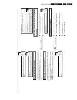
1
Switch
on
the
TV
set.
If
required,
select
the
programme
number
for
the
video
recorder.
2
Press
MENU
on
the
remote
control.
The
main
menu
will
appear.
3
Select
line
'
AUTO
STANDBY
'
using
P
r=
or
;q
P
.
4
Select
'
OFF
'
(no
automatic
switch-off)
or
'
ON
'
(automatic
switch-off)
with
the
menu
buttons
P
or
Q
.
5
Confirm
with
OK
.'
STORED
'
will
briefly
appear
on
the
TV
screen.
6
To
end,
press
MENU
.
Содержание VR570
Страница 12: ...Direction for use GB 12 VR120 3 3 Direction for use RT111 RT116 RT112 RT114 RT123 RT121 RT128 ...
Страница 15: ...Direction for use GB 15 VR120 3 SAT VR870L VR870CC VR720 Set width 435 mm ...
Страница 56: ...Service modes Repair tips GB 56 VR120 5 Engineer s remarks ...
Страница 60: ...60 VR120 6 Block diagrams Waveforms 6 4 Supply voltages and Bus diagram 1941 SAT MOUSE o M63100BFP ...
Страница 79: ...Circuit diagrams and PWB layouts Wiring diagram 79 VR120 7 7 16 Wiring Diagram Motherboard ...
Страница 80: ...80 VR120 7 Circuit diagrams and PWB layouts Wiring diagram 7 17 Mother board solder side 7172 CLOCK ADJUST ...
Страница 81: ...Circuit diagrams and PWB layouts Wiring diagram 81 VR120 7 Engineer s remarks ...
Страница 82: ...82 VR120 7 Circuit diagrams and PWB layouts Wiring diagram Engineer s remarks ...
Страница 83: ...Circuit diagrams and PWB layouts Wiring diagram 83 VR120 7 7 18 Mother board component side ...
Страница 119: ...Tape deck GB 119 VR120 10 ...
Страница 123: ...Tape deck GB 123 VR120 10 Engineer s remarks ...

