Direction for use
GB 43
VR120
3.
M
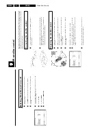
Before
you
call
an
engineer
If,
contrary
to
expectation,
you
have
any
problems
using
this
video
recorder,
it
may
be
caused
by
the
following
reasons.
You
will
find
the
phone
number
in
the
enclosed
guarantee
leaflet.
The
telephone
numbers
can
be
found
on
the
back
of
this
instruction
manual.
Have
the
model
number
(MODEL
NO)
and
the
production
number
(PROD.NO.)
of
your
video
recorder
ready.
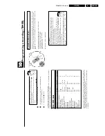
HOTLINE
telephone
numbers
The
telephone
numbers
for
after-sales
service
(HOTLINE)
are
also
saved
in
your
video
recorder.
To
call
them
up,
proceed
as
follows:
1
Switch
on
the
TV
set.
If
required,
select
the
programme
number
for
the
video
recorder.
2
Press
MENU
.
The
main
menu
appears.
3
Press
CLEAR
(CL)
.
The
after-sales
service
telephone
numbers
will
appear
on
the
screen.
4
Using
OK
,
you
can
select
more
telephone
numbers.
5
To
end,
press
MENU
.
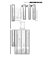
PROBLEM
SOLUTION
Your
video
recorder
does
not
respond
to
any
button
being
pressed:
b
There
is
no
power
supply:
check
the
power
supply.
b
A
programmed
recording
is
currently
being
made:
if
desired,
cancel
the
programmed
recording
with
STANDBY/ON
m
.
b
Child
lock
active:
switch
the
child
lock
off.
b
There
is
a
technical
problem:
disconnect
from
the
mains
power
supply
for
30
seconds,
then
connect
again.
If
this
doesn't
help,
you
could
reset
your
video
recorder
to
the
default
factory
settings.
Resetting
devices
to
default
factory
settings
b
Attention:
All
the
information
stored
(TV
channels,
time
and
date,
TIMER)
will
be
cleared.
1.
Disconnect
from
the
mains
power
supply.
2.
Press
and
hold
the
STANDBY/ON
m
button
on
the
device
and
reconnect
to
the
mains
power
supply.
3.
Release
the
button
when
'
OSD
'
appears
in
the
video
recorder
display.
Cassette
is
jammed
in
the
video
recorder:
b
Don't
use
force.
Pull
out
the
mains
plug
for
a
moment.
Remote
control
does
not
work:
b
Remote
control
not
pointed
toward
the
video
recorder:
point
it
at
the
video
recorder.
b
There
is
a
technical
problem:
Take
out
the
batteries,
wait
for
10
seconds
and
place
them
back.
b
Batteries
have
run
out:
change
the
batteries.
b
You
have
given
the
wrong
remote
control
command:
read
'Switching
remote
control
command'
in
chapter
'Additional
functions'.
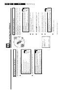
Switching
the
modulator
on
/
off
If
you
cannot
clear
picture
or
sound
interference
despite
optimisation,
you
can
switch
off
the
built-in
modulator.
Warning:
this
is
only
possible
if
you
have
connected
the
video
recorder
to
the
TV
set
with
a
scart
cable.
Without
a
scart
cable
you
will
not
receive
a
picture
fromthe
video
recorder
on
the
TV
set
when
the
modulator
is
switched
off.
1
Switch
on
the
TV
set.
If
required,
select
the
programme
number
for
the
video
recorder.
2
Press
STOP/EJECT
?
to
eject
any
cassette
that
might
be
in
the
device.
3
Press
the
STOP
h
button
on
the
remote
control.
Then
press
STOP/EJECT
?
until,
e.g.
'
M591
'
appears
in
the
display.
OPTIMIZE
MODULATOR
OPTIMIZE
FREQUENCY
591
p
MODULATOR
ON
SOUND
SYSTEM
G
________________________________
EXITpMENU
STOREpOK
4
Select
the
line
'
MODULATOR
'
o
n
the
TV
screen
or
'
MOD+
'
in
the
display
with
;q
P
or
P
r=
.
5
On
the
screen
select
'
OFF
'
o
r
in
the
display
'
MOD-
'
(modulator
off)
with
Q
.
How
can
I
switch
the
modulator
back
on?
In
the
display,
select
'
MOD+
'
(modulator
on)
with
Q
.
6
Confirm
with
OK
.
7
To
end,
press
MENU
.
Содержание VR570
Страница 12: ...Direction for use GB 12 VR120 3 3 Direction for use RT111 RT116 RT112 RT114 RT123 RT121 RT128 ...
Страница 15: ...Direction for use GB 15 VR120 3 SAT VR870L VR870CC VR720 Set width 435 mm ...
Страница 56: ...Service modes Repair tips GB 56 VR120 5 Engineer s remarks ...
Страница 60: ...60 VR120 6 Block diagrams Waveforms 6 4 Supply voltages and Bus diagram 1941 SAT MOUSE o M63100BFP ...
Страница 79: ...Circuit diagrams and PWB layouts Wiring diagram 79 VR120 7 7 16 Wiring Diagram Motherboard ...
Страница 80: ...80 VR120 7 Circuit diagrams and PWB layouts Wiring diagram 7 17 Mother board solder side 7172 CLOCK ADJUST ...
Страница 81: ...Circuit diagrams and PWB layouts Wiring diagram 81 VR120 7 Engineer s remarks ...
Страница 82: ...82 VR120 7 Circuit diagrams and PWB layouts Wiring diagram Engineer s remarks ...
Страница 83: ...Circuit diagrams and PWB layouts Wiring diagram 83 VR120 7 7 18 Mother board component side ...
Страница 119: ...Tape deck GB 119 VR120 10 ...
Страница 123: ...Tape deck GB 123 VR120 10 Engineer s remarks ...


