User’s Manual
4
Video Loop Through
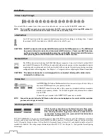
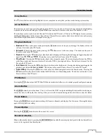
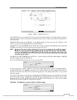
If you would like to connect your video source to another device, you can use the
Loop
BNC connectors.
NOTE: The Loop BNC connectors are auto terminated. Do NOT connect a cable to the Loop BNC unless it is
connected to a terminated device because it will cause poor quality video.
eSATA Port
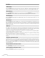
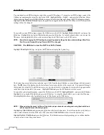
An eSATA port is provided to connect external storage devices for recording or archiving video. Connect
the external eSATA hard disk drive (RAID) cable to the eSATA port.
CAUTION: Do NOT connect or disconnect eSATA devices while the DVR power is on. The DVR must
be powered down to connect or disconnect eSATA devices. Power up eSATA devices
so they are ready for operation before powering up the DVR. Power down eSATA devices
after powering down the DVR and then disconnect eSATA devices.
Network Port
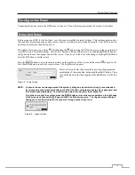
The DVR can be networked using the 10Mb/1Gb Ethernet connector. Connect a Cat5 cable with an RJ-45
jack to the DVR connector. The DVR can be networked with network cameras or video transmitters for remote
monitoring and recording, and can also be networked with a computer for remote monitoring, searching,
configuration and software upgrades. See
Chapter 3
─
Configuration
for configuring the Ethernet connections.
CAUTION: The network connector is not designed to be connected directly with cable or wire
intended for outdoor use.
Video Out
NOTE: Connect the monitor before the DVR boots so that video can be displayed on the monitor with the resolution
you have set during system setup.
Alarm Input/Output
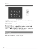
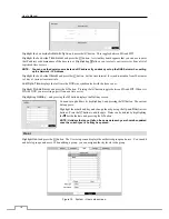
NOTE: To make connections on the Alarm Connector Strip, press
and hold the button and insert the wire in the hole below the button.
After releasing the button, tug gently on the wire to make certain it
is connected. To disconnect a wire, press and hold the button above
the wire and pull out the wire.
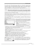
AI 1 to 16 (Alarm-In)
: You can use external devices to signal the DVR to react to events. Mechanical or electrical
switches can be wired to the
AI
(Alarm-In) and
GND
(Ground) connectors. The threshold voltage of electrical switches
for NC (Normally Closed) is above 2.4V and for NO (Normally Open) is below 0.3V, and should be stable at least 0.5
seconds to be detected. The voltage range of alarm input is from 0V to 5V. See
Chapter 3
─
Configuration
for configuring
alarm input.
An
HDMI
(High-Definition Multimedia Interface) connector is provided so that you
can use an HDMI monitor as your primary monitor.
A
VGA OUT
connector is provided so that you can use a standard, multi-sync computer
monitor as your primary monitor. Use the cable supplied with your monitor to connect
it to the DVR.
Connect the spot monitor to the
SPOT
OUT
connector as needed.


