background image

E-023-2-E

3.10 Menu: File (File)

The "File" menu can be used to connect communications (refer to section 3.2 "Starting and Connecting 

LinkTop), to disconnect (refer to section 3.3 "Ending the Connection", and 3.4 "Exiting LinkTop), as well 

as to set ports (refer to section 2.3 "Installing the Driver"), to create a flowmeter converter parameter 

database, and print parameters. This section describes the database and printing features.

3.10.1 Database

The various parameters, converter information, and so on inputted through the "Setup" menu (described 

in section 3.6) are stored in a database. This can be saved on a hard disk, floppy disk, or other type of 

storage medium.

Setting values can also be downloaded to the flowmeter converter.

3.10.1.1 Opening files

It is possible to load data from a saved file.

 Click the "File (F)" menu, and then select and click "Open File (O)" from the "Database (F)" drop-down  

list.

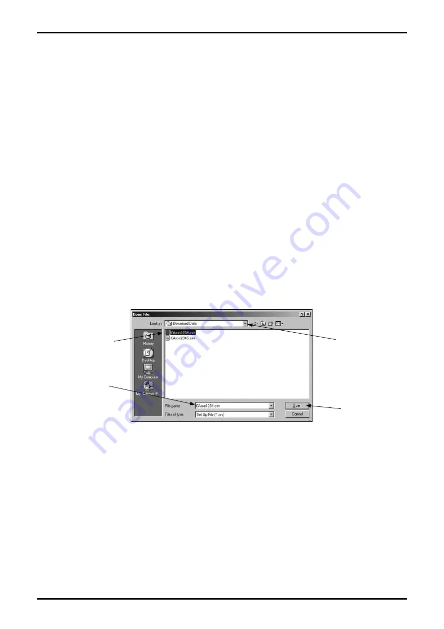
The common dialog box (Fig. 160) appears. Select the disk and folder which have the file to be opened 

from the drop-down list.

Select the file to open from the displayed files. Verify the "File Name (N)" and then click the "Open (O)" 

button. Click the "Cancel" button to exit without opening a file.

Select the file to open from the displayed files. Verify the "File Name (N)" and then click the "Open (O)" 

button. Click the "Cancel" button to exit without opening a file.

The selected file can be printed. For more information on printing, refer to section 3.10.2 "Printing".

3.10.1.2 Saving files.

It is possible to save the data set in the flowmeter converter to a file.

Click the "File (F)" menu, and then select and click "Save File (S)" from the "Database (F)" drop-down 

list.

Fig.160

Click here to open 

the selected file.

Click  the  icon  of 

the file to open.

A file name is 

displayed.

Click here to select 

a disk and folder.

Содержание EL 2310-08E Series

Страница 1: ...owmeter OVAL Coriolis Flowmeters Ins No E 023 2 E ALTImass Type U Type S Type B For the installation of application software LinkTop and the interface driver refer to Ins No E 020IMC Smart Communication Unit MODEL EL2310 Software Installation Procedure Manual ...

Страница 2: ...g Analog output 1 20 3 6 2 3 Analog output 2 setting Analog output 2 21 3 6 2 4 Pulse output 1 setting Pulse output 1 21 3 6 2 5 Pulse output 2 setting Pulse output 2 23 3 6 2 6 Status output setting Status output 23 3 6 2 7 Error output level settings Error output 25 3 6 3 Status input settings Status input 27 3 6 4 H L alarm setting H L alarm 29 3 6 4 1 H L alarm assignment H L alarm assign 29 3...

Страница 3: ...atus input loop test Fix Status input 54 3 7 3 Converter adjustment function Calibration 55 3 7 3 1 Automatic zero point adjustment Auto zero 55 3 7 4 Analog output adjustment Trim Analog 58 3 7 4 1 Analog output 1 adjustment Trim Analog 1 58 3 7 4 2 Analog output 2 adjustment Trim Analog 2 60 3 7 5 Cumulative total display control Counter Totalizer cntrl 60 3 7 5 1 Cumulative total 1 display and ...

Страница 4: ...is manual are the signal words NOTE CAUTION and WARNING as described in the examples below NOTE Notes are separated from the general text to bring the user s attention to important information CAUTION Caution statements signal the user about hazards or unsafe practices which could result in minor personal injury or product or property damage WARNING Warning statements signal the user about hazards...

Страница 5: ...out parameters and variables through interactive communications locally at the point of measurement or from a terminal in a remote location Using a Windows PC at hand you can monitor multiple windows on its screen The EL2310 operates on the application software LinkTop furnished CD ROM one LinkTop and driver Interface Adapter Fig 1 LinkTop for ALTImass 2 BEFORE YOU BEGIN 2 1 Inspection Upon Receip...

Страница 6: ...pment set up with associated equipment and devices are shown in Fig 2 NOTE In Fig 2 the customer is to supply the PC that meets the following requirements PC AT compatible DOS V machine Operating system is the Windows 2000 Windows XP Windows Vista Windows 7 RAM 8MB or larger Hard disk 10MB or larger Provision of USB port The receiving instrument in the figure above requires a load resistance 250Ω ...

Страница 7: ...m probe 500 approx Cable length from connector 1000 approx 50 Probe 60 Fig 3 2 3 PC Interface Adapter Comprised of components as shown in Fig 3 it converts the flowmeter transmitter signal Bell 202 into the USB signal All dimension in millimeters ...

Страница 8: ...ig 4 shows how the LinkTop window looks like Fig 4 Menu PC to Flowmeter Communications Status Title Bar Message Box Field The state of communications is indicated at bottom left of the screen by During communications RX WAIT Communications interrupted IDLE ...

Страница 9: ...er left of the PC screen and click LinkTop for Coriolis 3 J from Program Click Port setting I Ctrl I in File F at the top level menu of screen Set up the port Select the option labeled COM USB and click OK is the port number connected to the interface On seeting the screen like the one shown in Fig 7 click Connect C F3 in File F at the top level menu of screen At the message box as like the one in...

Страница 10: ...ected is automatically identified and the transmitter name appears in the title bar A message indicating ongoing communication appears at lower left of the screen with IDLE RX WAIT shown alternately Upon completion of connections a message box like the one in Fig 10 appears Click OK button When connection is complete of the menus at the top level menu of screen certain items that had been dimmed a...

Страница 11: ...l menu on the screen as shown in Fig 12 select Disconnect U Shift F3 and click on again At the message box as shown in Fig 13 click on OK This brings the connection between the flowmeter and LinkTop to come to an end Clicking on Cancel abandons the process of terminating the connection When connection is terminated part of the menu turns to be inactive characters turn to white in color as shown in...

Страница 12: ...p level menu of the screen select Exit E and click on again A message box as shown in Fig 15 appears If you are sure to exit the LinkTop click on OK button Clicking on OK button will cause the application window to disappear from the desktop To abort the terminating process click on Cancel ...

Страница 13: ...d Fig 17 Fig 17 If the Sensor type is CB or CS then Temp Outer will be added and Volume flow will not be shown 3 5 Menu Process Variables Processing Values Display The Process Variables menu can be used to confirm the flowmeter s process values instantaneous flow value fluid density fluid temperature cumulative total flow value and analog output as well as the Write Protect state For the actual sc...

Страница 14: ...converter writing state Write protect Click Process Variables V in the menu at the top of the screen and then select and click Write protect to display the following window Fig 18 Write protect indicates whether or not the converter is writeable Not write protected writeable Parameters can be modified and the various setting can be made Write protected not writeable Parameters cannot be modified a...

Страница 15: ...ty Refresh LCD Font Decimal Back light Contrast Key Setup Item Tree Fig 19 3 6 Menu Setup Settings The Setup menu can be used to set the flowmeter s various parameter values the converter s information and so on If a Diag Service window is displayed on the screen then it will not be possible to set the various parameters converter information and so on Close these window before making settings For...

Страница 16: ... 3 This functions both in the positive and negative directions In the Density section the density unit density damping gas multiphase flow determination density compensation and settled density can be set If the gas multiphase flow determination exceeds the setting value of the measurement density s Slug low limit or Slug high limit then this is seen as a gas multiphase flow and the flowmeter side...

Страница 17: ...is used to control valves or other such parts then change that control loop to manual control so that the control loop is in a state whereby it is not influenced by the flowmeter s output Click OK to change the settings to the inputted values and then click the OK button in the displayed message box Fig 22 to complete the setting process After the OK button is clicked the item input window will ap...

Страница 18: ...2 Set each item assignment Make your selections from the drop down lists by clicking the triangles on the right side of each item as shown in Fig 24 Fig 25 and Fig 26 If the Sensor type is CB or CS then the Pulse output 1 and Pulse output 2 selection items will be fixed at Mass flow and therefore will not be displayed Also when the Pulse output 2 selection items Double Pulse 90 Double Pulse 90 and...

Страница 19: ...n the pulse output assignment is modified the cumulative total will be reset and a confirmation message box will be displayed as shown in Fig 28 To avoid resetting the cumulative total click the Cancel button If you do not mind resetting the total click the OK button again Also note that if Cancel is clicked settings will not be modified Click OK to change the settings to the inputted values and t...

Страница 20: ...ule of thumb when making your settings When Lowcut is set to 0 0 the lowcut function is turned off 0 0 is the standard setting If anything other than flow mass or volume is assigned be sure to set 0 0 Also note that when Bi direction is selected the lowcut function will work in both positive and negative directions Click the OK button after all settings are completed to display the message box Fig...

Страница 21: ...up S menu and then select and click Analog output 2 from the Outputs drop down list Analog output 2 can be set by following the same procedures as described in 3 6 2 2 Analog output 1 steps to 3 6 2 4 Pulse output 1 setting Pulse output 1 Click the Setup S menu and then select and click Pulse output 1 from the Outputs drop down list The following window will be displayed Fig 34 Set pulse output 1 ...

Страница 22: ...icked in Fig 35 the cumulative total will be reset and a confirmation message box will be displayed as shown in Fig 36 To avoid resetting the cumulative total click the Cancel button If you do not mind resetting the total click the OK button again Also note that if Cancel is clicked settings will not be modified Click OK to change the settings to the inputted values and then click the OK button in...

Страница 23: ...bed in 3 6 2 4 Pulse output 1 steps to 3 6 2 6 Status output setting Status output Click the Setup S menu and then select and click Status output from the Outputs drop down list The following window will be displayed Fig 38 Set the status output function here Click the triangle on the right side of Status output func as shown in Fig 39 and select the function to set for status output from the drop...

Страница 24: ...m Error Status A function for switching status output when the item selected with Status output error select has an error status Bi direction A function for switching the status output when the flow mass and volume enters bidirectional mode the output increases with the flow regardless of the flow direction and the flow reverses If the Flow direction is Forward then the direction of the arrow on t...

Страница 25: ... the flowmeter s output Click OK to change the settings to the selected values and then click the OK button in the displayed message box Fig 41 to complete the setting process After the OK button is clicked the item input window will appear again Click the Cancel button to close the item input window To cancel the settings click the Cancel button in any step from to 3 6 2 7 Error output level sett...

Страница 26: ...the settings to the inputted values and to reflect the changed setting values in the flowmeter s output For the sake of safety if the flowmeter s output is used to control valves or other such parts then change that control loop to manual control so that the control loop is in a state whereby it is not influenced by the flowmeter s output Click OK to change the settings to the selected values and ...

Страница 27: ...unter Totalizer 1 2 Reset Counter Totalizer 1 and Reset Counter Totalizer 2 for status input 0 Signal Lock A function for locking each output by forcing a 0 setting Auto Zero A remote zero point adjustment remote zero function Reset Counter Totalizer 1 2 A function for resetting remote cumulative totals 1 and 2 Reset Counter Totalizer 1 A function for resetting remote cumulative total 1 Reset Coun...

Страница 28: ...such parts then change that control loop to manual control so that the control loop is in a state whereby it is not influenced by the flowmeter s output Click OK to change the settings to the selected values and then click the OK button in the displayed message box Fig 50 to complete the setting process After the OK button is clicked the item input window will appear again Click the Cancel button ...

Страница 29: ...ange the settings to the inputted values and to reflect the changed setting values in the flowmeter s output For the sake of safety if the flowmeter s output is used to control valves or other such parts then change that control loop to manual control so that the control loop is in a state whereby it is not influenced by the flowmeter s output Click OK to change the settings to the selected values...

Страница 30: ...larm point when the setting of Status output func is H L Alarm H L alarm includes the three types High alarm Low alarm and H L alarm Select the alarm type that matches your usage purpose High alarm Switches the status output when High alarm point is reached Low alarm Switches the status output when Low alarm point is reached H L alarm Switches the status output when either High alarm point or Low ...

Страница 31: ...er s output For the sake of safety if the flowmeter s output is used to control valves or other such parts then change that control loop to manual control so that the control loop is in a state whereby it is not influenced by the flowmeter s output Click OK to change the settings to the inputted values and then click the OK button in the displayed message box Fig 59 to complete the setting process...

Страница 32: ... information The following window will be displayed Fig 60 Set the converter information here Set each item For the items with a triangle on the right side click the triangle to make your selection from the drop down list as shown in Fig 61 and Fig 62 For the other items directly input a numerical value Fig 60 Fig 61 Fig 62 ...

Страница 33: ... settings are complete click the OK button to display a message box Fig 64 Click OK to change the settings to the inputted values and then click the OK button in the displayed message box Fig 65 to complete the setting process After the OK button is clicked the item input window will appear again Click the Cancel button to close the item input window To cancel the settings click the Cancel button ...

Страница 34: ...creen at a time so pick the items you want to see first and assign the numbers accordingly An item with the setting 0 is not displayed If a number is duplicated or skipped then an input error will occur and the setting will not be possible After all settings are complete click the OK button to display a message box Fig 67 Click OK to change the settings to the inputted values and then click the OK...

Страница 35: ...LCD as shown in Fig 70 and select the frequency to set from the drop down list After the setting is complete click the OK button to display a message box Fig 71 Click OK to change the settings to the selected values and then click the OK button in the displayed message box Fig 72 to complete the setting process After the OK button is clicked the item input window will appear again Click the Cancel...

Страница 36: ...shown in Fig 74 and select the font to set from the drop down list After the setting is complete click the OK button to display a message box Fig 75 Click OK to change the settings to the selected values and then click the OK button in the displayed message box Fig 76 to complete the setting process After the OK button is clicked the item input window will appear again Click the Cancel button to c...

Страница 37: ...less than 1000 then the decimal part will be displayed up to the 3rd position if it is 1000 or greater and less than 10000 then the decimal part will be displayed up to the 2nd position and if it is 10000 or greater and less than 100000 then the decimal part will be displayed up to the 1st position If the value is 100000 or greater then it will be displayed as an integer Integer The value will alw...

Страница 38: ...shown in Fig 82 and select the time to set from the drop down list Set the amount of time to keep the display screen s back light on here Off Back light remains in the off state On Back light remains in the on state Sleep 5min The back light turns off 5 minutes after the last key operation or after it turns on Sleep 10min The back light turns off 10 minutes after the last key operation or after it...

Страница 39: ...he item input window To cancel the settings click the Cancel button in any step from to 3 6 6 6 Display contrast setting Contrast Click the Setup S menu and then select and click Contrast from the LCD drop down list The following window will be displayed Fig 85 Set the contrast of displayed dots here Use the up down switch on the right side of the window to set the numerical value Range 1 to 63 Hi...

Страница 40: ...ing window will be displayed Fig 88 Set the sensitivity of converter keys and other items here Set each item Click the up down switches on the right side of items to change the numerical values For other items select ON or OFF Left key volume Sensitivity setting for the converter s left side keys Right key volume Sensitivity setting for the converter s right side keys Xmtr key protect Function for...

Страница 41: ...k the OK button in the displayed message box Fig 90 to complete the setting process After the OK button is clicked the item input window will appear again Click the Cancel button to close the item input window To cancel the settings click the Cancel button in any step from to Fig 90 ...

Страница 42: ... Menu Diag Service Checking and Adjustment Diag Service can be used to diagnose the flowmeter converter perform loop tests on each output adjust output values reset cumulative totals and calibrate sensor input When the Setup S windows are displayed on the screen it will not be possible to perform checks or adjustments So close them first Also note that other than Loop test the Diag Service T windo...

Страница 43: ... frequency range for approximately 5 seconds Input phase diff Conducts a check of the input phase difference range for approximately 1 second Input amplitude Conducts a check of the input amplitude range for approximately 1 second Input temp Conducts a check of the input temperature range for approximately 1 second These checks are performed in sequence starting from the top If there are no proble...

Страница 44: ...ancel button to close the window Clicking OK here will start the hardware check over again 3 7 1 1 2 Drive resistance check Drive coil check Click the Diag Service T menu select Self Diag from the Test Status drop down list and then click Drive coil check under that The following window will be displayed Fig 96 This will check the drive resistance Click OK after completely stopping the fluid Resis...

Страница 45: ... check a progress bar will appear as shown in Fig 98 allowing for the confirmation of the state of the check Click OK to execute the checks Once they are finished a message box Fig 99 will be displayed Click the OK button to complete the hardware check The results are displayed as shown in Fig 100 Click the OK button to return to the window from before the check and then click the Cancel button to...

Страница 46: ...n between CPUs to ensure that it is happening correctly for approximately 1 second Xmtr temp Conducts a check of the converter internal temperature for approximately 1 second These checks are performed in sequence starting from the top If there are no problems then OK will be displayed If there are problems NG will be displayed Click the OK button to display a message box Fig 102 This conducts che...

Страница 47: ...repeats the process one more time LED Tests the LED Turns red and green on 1 5 seconds each then turns them off for 1 5 seconds and repeats the process five more times Red and green are not turned on simultaneously LCD Tests the LCD Turns all dots on for 3 seconds then off for 3 seconds and then repeats the process one more time Click the OK button to display a message box Fig 106 Click OK to star...

Страница 48: ...he static device installation state Click OK after completely stopping the fluid Click the OK button to display a message box Fig 108 During the check a progress bar will appear as shown in Fig 109 allowing for the confirmation of the state of the check Click OK to execute the checks Once they are finished a message box Fig 110 will be displayed Click the OK button to complete the static device in...

Страница 49: ...he check and then click the Cancel button to close the window Clicking OK here will start the static device installation state check over again 3 7 1 2 2 Dynamic device installation state check Dynamic Click the Diag Service T menu select Installation from the Test Status drop down list and then click Dynamic under that The following window will be displayed Fig 112 This will check the dynamic dev...

Страница 50: ... window from before the check and then click the Cancel button to close the window Clicking OK here will start the dynamic device installation state check over again 3 7 2 Loop test Loop test Simulated output is created 3 7 2 1 Analog output 1 loop test Fix Analog 1 This test can be used to put analog output into a simulated output state and to verify the output line with a loop test Since this cr...

Страница 51: ...w shown in Fig 117 Click the OK button to cause the set analog value to be outputted While the simulated output value is being outputted a message at the bottom of the window will indicate that the system is creating simulated output as shown in Fig 119 Click the Stop button to halt the simulated output After the Stop button is clicked a message box Fig 120 will be displayed Click the OK button Cl...

Страница 52: ...e from the Loop Test drop down list The following window will be displayed Fig 121 Select the simulated output value and click the Start button To pick another pulse frequency to output select Other and click the Start button after inputting the pulse frequency The range of pulse frequency values that can be inputted is 0 1 to 11000 Hz Click the Cancel button to exit Fix Pulse Times in Fig 121 can...

Страница 53: ...cuted by following the same procedures as described in section 3 7 2 3 Fix Pulse 1 steps to 3 7 2 5 Status output loop test Fix Status output This puts status output into a simulated output state and conducts a loop test on the output line Since this creates simulated output regardless of the process state if the flowmeter s output is used to control valves or other such parts then for the sake of...

Страница 54: ...imulated output After the Stop button is clicked a message box Fig 128 will be displayed Click the OK button Clicking the OK button would return the interface to the window shown in Fig 125 so click the Cancel button to exit Fix Status output 3 7 2 6 Status input loop test Fix Status input This displays the state of status input Click the Diag Service T menu and then select and click Fix Status in...

Страница 55: ...o zero This adjusts the zero point of the flowmeter converter on the flowmeter side Click the Diag Service T menu and then select and click Auto zero from the Calibration drop down list The following window will be displayed Fig 130 Click the OK button after completely stopping the fluid Click the OK button to display a message box Fig 131 Fig 130 Fig 131 ...

Страница 56: ...f the window will indicate that the system is Adjusting Please wait as shown in Fig 132 Click OK to execute the zero point adjustment then click OK again in the message box Fig 133 displayed when adjustment is complete to exit automatic zero point adjustment The results are displayed as shown in Fig 134 Fig 132 Fig 133 ...

Страница 57: ...button to exit Autozero CAUTION Adjust the zero point when the temperature of the process fluid is stable at the temperature at which it will be used Also the sensor unit s internal process fluid must be in a completely halted state or it will not be possible to accurately adjust the zero point adjustment ...

Страница 58: ...ice T menu and then select and click Trim Analog 1 from the Trim Analog drop down list A message box Fig 135 will be displayed Click the OK button to adjust analog output 1 The following window will be displayed after the OK button is clicked Fig 136 Select the scale from 4 to 20mA for adjusting analog 1 or select another scale Other scale then click the OK button When the 4 to 20mA scale is used ...

Страница 59: ... the 4mA adjustment Click the Cancel button to exit analog output value adjustment Click the OK button when the Adjustment is finished message box appears as shown in Fig 138 Click the Cancel button to halt adjustment in progress and follow the instructions that appear When Other scale is selected in the window shown in Fig 136 another scale can be inputted as shown in Fig 139 When an analog value...

Страница 60: ...log output value adjustment Click the OK button when the Adjustment is finished message box appears as shown in Fig 138 Click the Cancel button to halt adjustment in progress and follow the instructions that appear 3 7 4 2 Analog output 2 adjustment Trim Analog 2 This adjusts the output value of the flowmeter converter s analog output 2 Analog output 2 can be adjusted by following the same method ...

Страница 61: ...lowmeter will be treated as the positive direction and if it is Reverse then the opposite direction of the arrow on the flowmeter will be treated as the positive direction This window can be used to Start Stop or Reset the cumulative total Note that Start Stop and Reset only affect the cumulative total and do not work on the pulse output Selecting Reset will cause the window to appear as shown in ...

Страница 62: ...l temperature as well as a log of errors that occur during operation It is also possible to display the length of time the converter has been running display elapsed time make settings and so on The actual screen is as shown in Fig 143 Maintenance Maintenance xmtr Error log Xmtr temp log Xmtr temp History Fig 143 Maintenance Item Tree ...

Страница 63: ...e 64 latest log entries will be shown Input a value into Input address and click the OK button to display a message box Fig 145 Click the OK button again to display the last 64 entries in the log corresponding to the Input address Current address shows the address of the most recent log entry To display the most recent log entry input the Current address value into Input address or input 3000H To ...

Страница 64: ...click Xmtr temp log from the Maintenance xmtr drop down list The following window will be displayed Fig 147 The converter s internal temperature is saved to the log approximately once every 2 minutes and log entries begin to be repeatedly overwritten after 64 entries are saved If the converter s internal temperature exceeds 90 then an Xmtr temperature alarm will occur and after 32 log entries are ...

Страница 65: ...e Save button to display Fig 151 specify the save location and file name and then click OK to create a CSV file completing the save process Click Cancel to close the Xmtr temp log window 3 8 1 3 Converter internal temperature display Xmtr temp Click the Maintenance M menu and then select and click Xmtr temp from the Maintenance xmtr drop down list A window such as the one shown in Fig 152 will app...

Страница 66: ... note that the changed date and other values are reflected in the log data Note however that time stops while the power is off so a discrepancy will arise After the setting is complete click the OK button to display a message box Fig 154 Click OK to change the settings to the selected values and then click the OK button in the displayed message box Fig 155 to complete the setting process Click the...

Страница 67: ...tly displayed windows The options for arranging windows are Cascade TileHorizontal and TileVertical For instance assume that multiple windows are being displayed on top of each other as shown in Fig 156 Select Cascade to display these windows stacked as shown in Fig 157 Fig 156 Fig 157 ...

Страница 68: ...E 023 2 E 68 Select TileHorizontal to display these windows lined up vertically as shown in Fig 158 Select TileVertical to display these windows lined up horizontally as shown in Fig 159 Fig 158 Fig 159 ...

Страница 69: ... file Click the File F menu and then select and click Open File O from the Database F drop down list The common dialog box Fig 160 appears Select the disk and folder which have the file to be opened from the drop down list Select the file to open from the displayed files Verify the File Name N and then click the Open O button Click the Cancel button to exit without opening a file Select the file t...

Страница 70: ...y clicking it Verify the File Name N and click the Open O button To exit without deleting the file click the Cancel button After the click the selected file will open and a message box Fig 163 will be displayed To delete click the Yes Y button To not delete click the No N button After the Yes Y button is clicked the file will be deleted Fig 161 Fig 162 Fig 163 Click to delete the file Input the fi...

Страница 71: ... stored from the drop down list Select the file to download by clicking it Verify the File Name N and click the Open O button To exit without downloading the file click the Cancel button A message box Fig 165 will be displayed Click the OK button to download the data to the converter To not download the data click the Cancel button Once the data is downloaded the various setting values will be mod...

Страница 72: ...d is complete a message box Fig 167 will be displayed Click the OK button Verify the downloaded settings Disconnect communications as described in section 3 3 Ending the Connection Next reconnect communications by following the instructions in section 3 2 Starting and Connecting LinkTop Verify that the settings have been changed to the downloaded settings by following the instructions in section 3...

Страница 73: ...Fig 168 Verify the various parameter values here and either click the Print button to print or the Close button to not print To set the margins input the value for the left margin and click the Apply button Once the Print button is clicked a table will be printed as shown in Fig 169 The printer to use for printing can be set the items from the PC s Start menu Settings Control Panel Printers Fig 16...

Страница 74: ... output OFF Damp 4 0 sec Error output Slug low limit 0 000 g ml Slug high limit 10 000 g ml Analog Downscale Slug durattion 0 sec Pulse Zero 0Hz Density compensation OFF Flow Cal Standard temp 20 00 Expansion coef 0 00024 SK20 56 05967 MHz kg h Settled density OFF SKM 1 000000E 0 Density value 1 0000 g ml SKt 4 440000E 4 Temperature Cal temp 20 00 Cal freq 150 000 Hz Unit SKfa 0 000000E 0 Damp 4 0...

Страница 75: ...d Connecting LinkTop Is the smart communication unit s probe or unit disconnected Is the flowmeter converter receiving power 3 11 2 If it is not possible to connect to the flowmeter If when the flowmeter is connected as described in section 3 2 Starting and Connecting LinkTop a converter not supported by this application software is connected then the message box shown in Fig 171 will appear Click...

Страница 76: ... is in the setting on the converter side If a mistake is discovered in LinkTop settings after the setting items are inputted and the OK button is clicked then the error box shown in Fig 172 will be displayed Click the OK button and correct the mistaken input If a mistake is discovered in settings on the converter side after the setting items are inputted and the OK button is clicked then the error...

Страница 77: ...nnot be taken normally Bring the density within the lower and upper range limits P O Sig Error 1 Pick off signal voltage is outside the normal range and measurements cannot be taken normally Bring the LPO and RPO voltage values within the range of 0 to the pick off upper limit Temperature Connect Error 1 Cannot verify a normal connection with the temperature sensor Bring the temperature resistance...

Страница 78: ...larm point or lower H L Alarm occurs when any of the conditions described above are met When something other than H L Alarm is set for Status Output func If High Alarm or H L Alarm is set for H L Alarm type and the measurement value set for H L Alarm Assign is High Alarm point H L Alarm hys or lower If Low Alarm or H L Alarm is set for H L Alarm type and the measurement value set for H L Alarm Ass...

Страница 79: ...Basic unit 50W 20H 35D in mm Probe 1500mm approx fixed to the interface itself Housing Plastic black Communication protocol HARTTM protocol Communication terminal resistance Load resistance 250Ω min Upper limit depends on flowmeter s transmitter specifications Functions Monitors flowmeter transmitter output Reads sets up and saves parameters Stored in FD HD or other external Trims analog outputs C...

Страница 80: ...E 023 2 E All specifications are subject to change without notice for improvement 2011 12 Revised 2011 05 Released E 023 2 E 1 ...

Отзывы: