E-023-2-E
20
⑥
After the "OK" button is clicked, the item input window will appear again. Click the "Cancel" button to
close the item input window.
To cancel the settings, click the "Cancel" button in any step from
②
to
④
.
3.6.2.2 Analog output 1 setting (Analog output 1)
①
Click the "Setup (S)" menu, and then select and click "Analog output 1" from the "Outputs" drop-down
list.
②
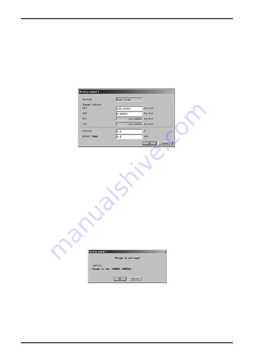
The following window will be displayed (Fig. 31). Set analog output 1 here.
③
Set each item. USL (the sensor
’
s upper limit) and LSL (the sensor
’
s lower limit) indicate the input
range of URV (20mA setting) and LRV (4mA setting), so use this as a rule of thumb when making your
settings.
When "Lowcut" is set to "0.0%", the lowcut function is turned off. "0.0%" is the standard setting. If
anything other than flow (mass or volume) is assigned, be sure to set 0.0%. Also note that when "Bi
direction" is selected, the lowcut function will work in both positive and negative directions.
④
Click the "OK" button after all settings are completed to display the message box (Fig. 32).
Click "OK" here to change the settings to the inputted values, and to reflect the changed setting values
in the flowmeter
’
s output. For the sake of safety, if the flowmeter
’
s output is used to control valves or
other such parts, then change that control loop to manual control so that the control loop is in a state
whereby it is not influenced by the flowmeter
’
s output.
Fig.31
Fig.32


