enabling
innovative
electronics
Ossila Ltd
Copyright © 2009-2015
75
Partition method
In order to automatically estimate the mobility with the
partition method
, SuperFACT executes the
following algorithm,
1.
The input and output points defining the Transfer Characteristics curves (
V
GS,i
,
I
DS,i
) are
divided into subsets of
N
point each, with 5≤
N≤10
User’s defined quantity specified on
Advanced SMU and Acquisition Settings
with
Partition Method: Set Size
control.
2.
For each subset, the Best Linear Fit and its respective slope are estimated.
The mobility is then computed using Eq. (4) for the Transfer Characteristic in Linear Regime,
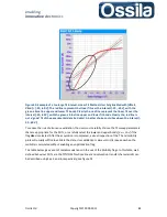
and Eq. (8) for the Transfer Characteristic in Saturation Regime, see figure 26.
3.
The resulting mobility
is then plotted as function of the gate voltage, with
median pints of the data point subsets used to calculate the liner fits.
4.
For both linear and saturation regime, the maximum mobility is highlighted on the mobility
plot and reported on the data file providing that the linear fit R-squared parameter is larger
than a User’s defined threshold specified on
Advanced SMU and Acquisition Settings
through the
Partition Method: R-squared
control.
(The recommended value of R-squared
for this algorithm is 0.99). If no data-point set satisfies this condition, the mobility plot turns
red with an exclamation mark in the plot legend flagging which mobility does not fulfil this
requirement. A warning message flag is also logged in the data file by printing an
acclamation mark next to device number.
For each linear fit, SuperFACT calculates also the
Upper
and
Lower Bounds
of the fit at a 0.95
confidence level, see figure 26, whose meaning is the following:
There is a 95% probability that the
actual
best linear fit lies in the region demarcated by the
upper and lower bounds, where the blue dashed line represent the linear fit bounds
Figure 26. Linear Fit (Red, solid line) and Upper and Lower Bound defining the confidence
interval (dashed blue line) for two subsets of input (Gate Voltages) and measured point (Drain
Current) for TC in Saturation Mode.

