enabling
innovative
electronics
Ossila Ltd
Copyright © 2009-2015
37
|V
DS
|<< |V
GS
– V
Th
| and |V
GS
| > |V
Th
|.
Eq. 2
Eq. 2 defines the
range
or
region of validity
of Eq. 1. In the range of validity of Eq. 1, V
DS
is small
compared to V
GS
and, therefore it follows that this equation can be simplified as
.
Eq. 3
By inverting Eq. 3, the mobility
can be written as
,
Eq. 4
where
is the slope of the curve I
DS
(V
GS
), see Fig. 5. Eq. 6 is the equation SuperFACT uses to
calculate the field effect linear mobility.
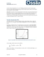
Since the mobility is proportional to the slope of the linear transfer characteristic curves, it follows
that these curves can be written as
.
Eq. 5
Figure 16. The linear mobility is proportional to the slope α of the IDS(VGS) curves, while the
threshold voltage is the intercept of these curves with the x-axis (red dot on the picture).
The field effect mobility can then be calculated by fitting the (I
DS,i
,V
DS,i
) points
10
satisfying Eq. 3 to a
straight line, the slope of which is inserted into Eq. 4 in order to obtain
µ
, while the intercept with
the
x
-axis gives the threshold voltage.
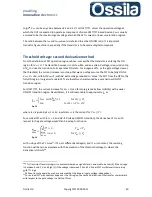
The mobility is the most important figure of merit for FET since it determines the ON/OFF speed of
the transistor, see Eq. 16.
10
Here, the extra index
i
is added to underline that (I
DS,i
,V
DS,i
) are experimental quantities, with V
DS,I
the nth
drive voltage and I
DS,I
the corresponding nth measured current.

