enabling
innovative
electronics
Ossila Ltd
Copyright © 2009-2015
65
Auto Zero
sets the Auto Zero for the GATE SMU, refer to the IV GATE section above for more
information.
For both
V
DS
(Linear and Saturation regime) the Gate sub-panel is used to determine the start, end
and measurement points of the Transfer Characteristic curves
I
DS
(
V
GS
) by means of the controls
V
GS
Start
,
V
GS
End
, and
ΔV
GS
, respectively.
I
DS
(
V
GS
) is measured at
, with
,
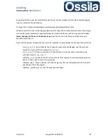
Eq. 24
with
and
N
number of data points (number of steps).
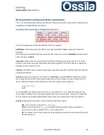
N
is given by
Eq. 25
Note:
Since the TC data is used to estimate the mobility and due to the nature of the mobility
computation algorithm, see
Mobility Computation
below, it is advisable to measure the drain
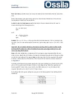
current for (at least) each Volts change in the gate potential, i.e.
≤
and, in any case, acquire
no less than
50/60 data points.
Current Limit
specifies the maximum gate current (
I
GS
) that the GATE source generated across the
target as the User’s selected drain voltages are applied to the target itself, i.e. Current Limit refers to
I
GS
(
V
GS
) for any
V
DS
applied.
Delay
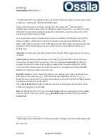
is the PXIGATE settling time. For each data point, the current
is acquired after a time
t
=Delay has elapsed from the application of gate voltage
.
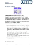
Acquisition settings: Transfer characteristics (IV), Gate
This panel control the GATE SMU for TC sweeps.
SMU Name
is the alias name of the SMU unit as specified in MAX (Measurement & Automation
Explorer).
For Keithley series 26XX dual channel series, the SMU alias name must be
KeithleyO
, while for NI PXI
4132, the name is
SMUB
.
Channel
is the SMU channel used for output/input operation. Input
b
for Keithley 26XX dual channel
series and
0
for NI PXI 4132.

