enabling
innovative
electronics
Ossila Ltd
Copyright © 2009-2015
16
Multiplexer Measurement Unit
Front panel & substrate placement
The Multiplexer measurement Unit contains the control and signal circuitry. It uses the NI 6501 OEM
Board to communicate with the computer. The NI 6501 OEM Board also supplies the power to the
Multiplexer Unit via the USB connection to the computer.
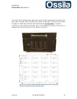
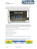
To access the substrate holder, open the multiplexor lid, see figure 2. The holder consists of a push-
fit bracket and a 2D array of twenty-eight POGO
©
probes. When a substrate is placed in the holder
with the lid secured with its four screws, the probes provide low-resistance contact with all the
device and gate pads on the substrate.
Figure 2. Substrate holder containing twenty Drain/Source probes and eight Gate probes.
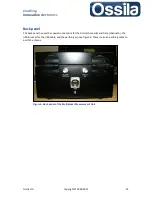
The Gate connections are provided by the bottom row, i.e. by the row nearest to the front panel of
the Multiplexer Unit, see figure 2. It follows that the substrate must be placed (face-down) with the
gate side nearest to the front panel, see figure 3.
Row of Gate
Probes
5 rows of Drain Probes

