enabling
innovative
electronics
Ossila Ltd
Copyright © 2009-2015
24
NI 6501 OEM outputs
The Multiplexer Measurement Unit is controlled by the NI 6501 board. At the NI 6501 board startup
and reset, the hardware sets all DIO (digital I/O) lines to high-impedance inputs. As each line has a
weak pull-up resistor of 4.7kOhm connected to it, all pins are set to HIGH. The default output
configuration of the port pins is open-drain. This configuration allows the digital output signal to
swing to 5V. Each port pin can be programmed as a digital input or output. To operate the system,
the DIO lines should be programmed as digital outputs
The USB 6501 input/ouput signal is constituted of 24 independent DIO lines (or channels) arranged
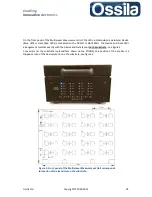
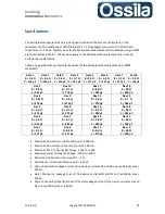
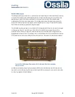
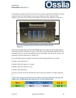
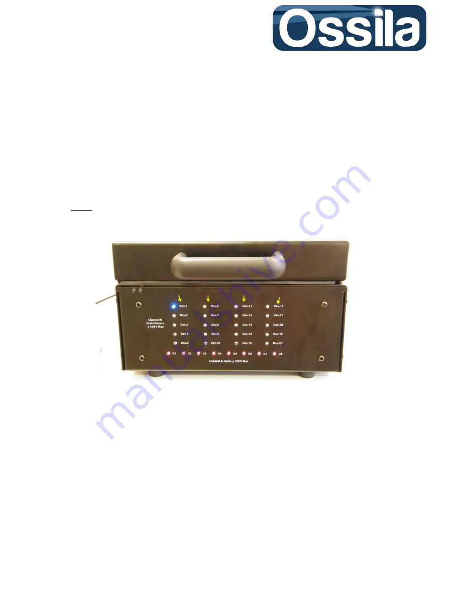
in three groups of eight. Four DIO lines ( P0.0, P0.1, P0.2 and P0.3) are assigned to select to a
particular Device column, see figure 8, while the DIO lines used to address each single Device are
shared between two columns. For example, Dev 1 is controlled by the column line P0.0 and row line
P0.4, while Dev 16 is turned on/off by the lines P0.3 and P.04. The Gates ( G1,G2,G3, G4,G5,G6,G7
and G8) are addressed using an exclusive (single) DIO channel. Additionally, two DIO channels are
reserved to control the Security Bits. See section
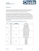
Digital DIO Lines
below for more details instruction
son how to programme the Multiplexer.
Column 1
Column 2
Column 3
Column 4
Figure 8. The Multiplexer Measurement Unit addresses Devices by assigning
Device columns.


