enabling
innovative
electronics
Ossila Ltd
Copyright © 2009-2015
79
the set of measured (I
DS,i
,V
GS,i
) complying with the FET standard model, with V
DS
chosen
in a
manner such that the DUT operates in saturation regime, and with the gate voltage values
satisfying the inequality V
Start
≤
V
GS,i
≤
V
End
, with
V
Start
> V
Th
and
, or
V
End
≤
.
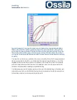
Figure 29. Linear and saturation TC curves and their interval of validity.
Mobility algorithm: optimisation flags
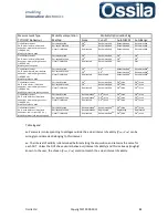
The optimisation flags of the mobility algorithms implemented in SuperFACT attempt to locate the
validity interval [V
Start,
V
End
] for each DUT automatically using the measured data (I
DS,i
,V
GS,i
) as input.
Important:
SuperFACT automatically excludes any I
DS
in compliance.
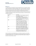
Flag 0:
None.
No optimisation routine is enabled.
Note:
The mobility will be calculated for each V
GS,i
> V
DS
(linear regime) or for V
GS,i
> V
1%
, where V
1%
is
the voltage at which drain current I
DS
is 1% of its maximum I
MAX
. These two conditions prevent
calculating the figures of merit over data acquired when the transistor is operating in the
subthreshold
region (OFF).
Flag 1:
Use
r.
The User manually enter the validity interval [V
Start,
V
End
], and the mobility is calculated
only over this interval. This option is useful when all working DUTs, on the substrates, show similar
transfer curves whose features are broadly known a priori.

