enabling
innovative
electronics
Ossila Ltd
Copyright © 2009-2015
78
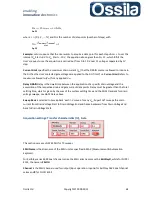
the voltage stress causes a drain current with negative slope at large gate voltage only, i.e. for
with
large when compared with
V
Th
, SuperFACT will still return the FET figures of
merit for the (I
DS,i
,V
GS,i
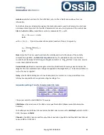
) satisfying Eq. 30 and the additional condition
For the purpose of FET characterisation, the SuperFACT Interval of validity [
V
Start
,
V
End
], i.e. the
portion of the transfer curves used to calculate the FET figures of merits, is therefore defined as
the set of measured (I
DS,i
,V
GS,i
) complying with the FET standard model, with V
DS
chosen in a
manner such that the DUT operates in linera regime, and with the gate voltage values
satisfying the inequality V
Start
≤
V
GS,i
≤
V
End
.
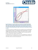
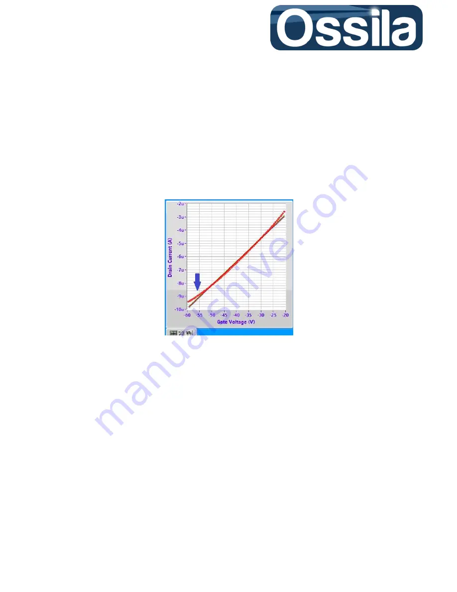
Figure 28. TC Linear Current for a p-type OFET. The red dots are the measured data; while the
continuous black line is the linear fit and the thin green and yellow lines (barely visible) are the
upper and lower bound of the linear fit. The arrow indicates an incipient voltage stress for VGS < -
50 V. For severe drain current degradation, the current IDS will decrease as the gate voltage
increases (in absolute value).
For the linear regime,
V
Start
must be larger than the threshold voltage V
Th
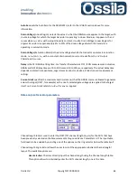
, with the extra condition
>>
, see Eq. 31. Conversely, V
End
<
. If no current degradation is present, V
End
=
V
GS End
with V
GS End
the largest voltage swept.
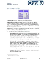
Similarly to the linear regime, for the saturation regime, the gate voltage must satisfy the
condition
. By reordering the first inequality in Eq. 6, the condition for V
End
can be found
to be
Eq. 31
In case of current degradation, the same considerations as for the linear case apply. The interval of
validity for the saturation mode figure of merits calculates is therefore defined as, see figure 29,

