background image

Installing the Switch

57

FIGURE:

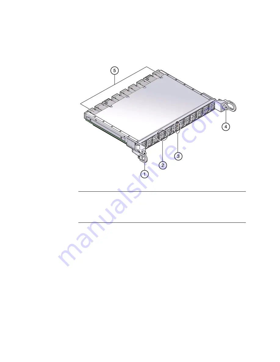
Line Card Features

3. Inspect the line cards.

See

“Inspect the Line Card Chassis for Installation” on page 58

.

Related Information

“Identify the Fabric Cards for Installation” on page 52

“Identify the InfiniBand Cable for Installation” on page 61

Figure Legend

1

Left retainer bolt

2

CXP connectors

3

Status LEDs

4

Right retainer bolt

5

XBOW connectors

Содержание Sun Datacenter InfiniBand Switch 648

Страница 1: ...Sun Datacenter InfiniBand Switch 648 Installation Guide Part No 820 7738 12 May 2010 Revision A ...

Страница 2: ...és sous licence et soumis à des restrictions d utilisation et de divulgation Sauf disposition de votre contrat de licence ou de la loi vous ne pouvez pas copier reproduire traduire diffuser modifier breveter transmettre distribuer exposer exécuter publier ou afficher le logiciel même partiellement sous quelque forme et par quelque procédé que ce soit Par ailleurs il est interdit de procéder à tout...

Страница 3: ...r and Pins 4 Serial Management Connector and Pins 5 CXP Connector and Pins 5 Routing Service Cables 7 Power Cord Requirements 8 Management Cable Requirements 9 Understanding InfiniBand Cabling 9 InfiniBand Cable Cautions 10 InfiniBand Cable Guidelines 11 InfiniBand Cable Types 12 InfiniBand Cable Path Lengths 12 InfiniBand Cable Bundling 13 Floor and Underfloor Delivery of InfiniBand Cables 14 Ove...

Страница 4: ...20 Installation Responsibilities 20 Installation Sequence 20 Installing the InfiniBand Software Stack 23 Install the HPC Software Suite 23 Unpacking the Chassis 25 Remove the Shipping Carton Contents 25 Unsecure the Chassis From the Pallet 28 Preparing the Chassis 29 Install the Rail Assemblies in the Rack 29 Install the Cable Trees 32 Install the Cable Curves 38 Install the Chassis in the Rack 39...

Страница 5: ...tainer Bolts for Installation 58 Inspect the Line Card XBOW Connectors for Installation 59 Inspect the Line Card CXP Connectors for Installation 60 Inspecting the InfiniBand Cables for Installation 61 Identify the InfiniBand Cable for Installation 61 Inspect the InfiniBand Cable Hardware for Installation 62 Inspect the InfiniBand Cable Connectors for Installation 63 Installing the Components 63 In...

Страница 6: ...ds for Installation 93 Create the guid txt File for Installation 93 Power On the Fabric Cards for Installation 96 Check the Fabric Card Status LEDs 96 Verify the Fabric Card Status 97 Identify the Fabric Card Addresses 99 Display the Fabric Card FRU ID Information 100 Powering On the Line Cards 101 Enable the Line Cards for Installation 102 Power On the Line Cards for Installation 103 Check the Li...

Страница 7: ...s 117 Display the InfiniBand Cable FRU ID Information 118 Verifying the InfiniBand Fabric 119 Discover the InfiniBand Fabric Topology 120 Perform Diagnostics on the InfiniBand Fabric 121 Validate the InfiniBand Fabric and Report Errors 123 Index 125 ...

Страница 8: ...viii Sun Datacenter InfiniBand Switch 648 Installation Guide May 2010 ...

Страница 9: ...ted Documentation The documents listed as online are available at http docs sun com app docs prod ib switch 648 Application Title Part Number Format Location Getting started Sun Datacenter InfiniBand Switch 648 Getting Started Guide 820 7745 Printed PDF Shipping kit Online Last minute information Sun Datacenter InfiniBand Switch 648 Product Notes 820 7743 PDF Online Preparation and installation Su...

Страница 10: ...docs sun com Include the title and part number of your document with your feedback Sun Datacenter InfiniBand Switch 648 Installation Guide part number 820 7738 12 Command reference Sun Datacenter InfiniBand Switch 648 Command Reference 820 7741 PDF HTML Online Compliance Sun Datacenter InfiniBand Switch 648 Safety and Compliance Guide 820 7744 PDF Online ILOM information Oracle Integrated Lights O...

Страница 11: ...e Switch on page 15 Switch Administration Switch Remote Management Switch Service Switch Reference Understanding Switch Specifications These topics describe the specifications of the switch and the connectors found on the switch components and the pinouts of those connectors Physical Specifications on page 2 Environmental Requirements on page 3 Acoustic Noise Emissions on page 3 Electrical Specifi...

Страница 12: ...bles on page 7 Understanding InfiniBand Cabling on page 9 Physical Specifications Related Information Remove the Shipping Carton Contents on page 25 Install the Chassis in the Rack on page 39 Dimension Measurements Width 17 56 in 446 0 mm Depth 27 in 685 8 mm Height 19 25 in 489 mm Weight 410 0 lbs 186 kg ...

Страница 13: ...t bulb Elevation Sun requirement Maximum 9840 feet 3000 meters at 104 F 40 C Parameter Operating Idling Acoustic power LWAd 1B 10dB 7 1 B 7 2 B Acoustic pressure LpAm 58 9 dBA 59 0 dBA Parameter AC Version Requirement Voltage 200 VAC to 240 VAC single phase 47 63 Hz Current per input 20 A maximum per input at 200 VAC Current total 32 A maximum total for all inputs at 200 VAC Power 6400 Watt Total ...

Страница 14: ...e following table lists the pinout of the network management connector Related Information Management Cable Requirements on page 9 Attach the Management Cables on page 76 Access the CMC From the Network Management Port on page 84 Pin Signal 1 TXD 2 TXD 3 RXD 4 Not used 5 Not used 6 RXD 7 Not used 8 Not used ...

Страница 15: ...t connector Related Information Management Cable Requirements on page 9 Attach the Management Cables on page 76 Access the CMC From the Serial Management Port on page 82 CXP Connector and Pins The CXP connector supports three InfiniBand 4X ports through 84 pins Pin Signal 1 RTS 2 DTR 3 TXD 4 GND 5 GND 6 RXD 7 DSR 8 CTS ...

Страница 16: ... GND 25 GND 46 GND 67 GND 5 TX2p 26 TX3p 47 RX1p 68 RX0p 6 TX2n 27 TX3n 48 RX1n 69 RX0n 7 GND 28 GND 49 GND 70 GND 8 TX4p 29 TX5p 50 RX7p 71 RX6p 9 TX4n 30 TX5n 51 RX7n 72 RX6n 10 GND 31 GND 52 GND 73 GND 11 TX6p 32 TX7p 53 RX5p 74 RX4p 12 TX6n 33 TX7n 54 RX5n 75 RX4n 13 GND 34 GND 55 GND 76 GND 14 TX8p 35 TX9p 56 RX11p 77 RX10p 15 TX8n 36 TX9n 57 RX11n 78 RX10n 16 GND 37 GND 58 GND 79 GND 17 TX10...

Страница 17: ...CC12 Rx Signal Description GND Ground for both signal and power return VCC3 3 Tx 3 3V standby power from the power supplies VCC3 3 Rx 3 3V standby power return VCC12 Tx 12V power for cable export and future enhancements VCC12 Rx 12V power return TXportdiff Differential InfiniBand transmit signal where port 0 to 11 diff n or p for negative or positive RXportdiff Differential InfiniBand receive sign...

Страница 18: ...upplies 0 and 1 and B source feeding power supplies 2 and 3 Your switch shipping kit should contain four power cords that are specific to your country or application The following table describes the power cords available Caution Only install and route power cabling in a matter that complies to federal state and local electrical codes Related Information Electrical Specifications on page 3 Attach ...

Страница 19: ...age of the NET MGT connection is that administration of the switch can happen from anywhere on the network There is no cable length constraint for the network management route because of the re amplification filtering and processing that happens at each hub or switch within the Ethernet network No network management cable should be more than 100 m long Serial device adapters enable you to use an E...

Страница 20: ...kink might occur Hold the coil closed as you unroll the cable pausing to allow the cable to relax as it is unrolled Do not step on the cable or connectors Plan cable paths away from foot traffic or rolling loads Do not pull the cable out of the shipping box through any opening or around any corners Unroll the cable as you lay it down and move it through turns Do not bend the cables to a radius tig...

Страница 21: ...ius for copper cables Find alternative routes for turns that are tighter 4 Secure the cable to hard points and bundle it with soft hook and loop fasteners See InfiniBand Cable Bundling on page 13 5 Mediate the slack between securing points to maintain minimal cable tension and proper support Do not straighten the cable to correct a bend that is too tight Leave the cable bend as is Do not hang the ...

Страница 22: ...n page 12 Connecting InfiniBand Cables on page 108 CXP Connector and Pins on page 5 InfiniBand Cable Path Lengths Cable paths should be as short as possible When the length of a cable path has been calculated select the shortest cable to satisfy the length requirement When specifying a cable consider the following Bends in the cable path increases the required length of the cable Rarely does a cab...

Страница 23: ... use hook and loop straps to keep cables organized If possible use color coordinated straps to help identify cables and their routing The InfiniBand splitter and 4X copper conductor cables are fairly thick and heavy for their length Consider the retention strength of the hook and loop straps when supporting cables Bundle as few cables as reasonably possible If the InfiniBand cables break free of t...

Страница 24: ...s on page 11 Overhead Delivery of InfiniBand Cables on page 14 Connecting InfiniBand Cables on page 108 Overhead Delivery of InfiniBand Cables For overhead delivery it is suggested that cable shelves and lattices be used to support the InfiniBand cables If the overhead delivery has a large drop height consider using an intermediate support for the InfiniBand cables Use of the support can limit the...

Страница 25: ...age 45 Installing the Components on page 63 Powering On the CMCs on page 75 Powering On the Fabric Cards on page 92 Powering On the Line Cards on page 101 Connecting InfiniBand Cables on page 108 Verifying the InfiniBand Fabric on page 119 Related Information Preparing the Site on page 1 Switch Administration Switch Remote Management Switch Service Switch Reference Understanding the Installation T...

Страница 26: ...inistrative commands Switch Service understanding service procedures Supported Configurations The switch is sold with two configurations ATO and fully populated With an ATO configuration you must configure the quantity of fabric cards and line cards at the time of ordering With a less than a fully populated switch fabric card fillers and line card fillers are automatically included in the order to...

Страница 27: ...e 96 Line Card Distribution on page 17 Fabric Card Handling Guidelines Fabric cards use high density XBOW connectors that interface with the midplane pins If these connectors are damaged the pins of the midplane connector can also be damaged upon fabric card insertion You must inspect the fabric card chassis retainer bolts fans and connectors before installing the fabric card into the switch chass...

Страница 28: ...connector can also be damaged upon line card insertion You must inspect the line card chassis retainer bolts and connectors before installing the line card into the switch chassis Caution Lift line cards by their handles or by their sides Do not lift line cards by their XBOW connectors or allow the XBOW connectors to strike any object Related Information Fabric Card Handling Guidelines on page 17 ...

Страница 29: ...are the following The environment where the switch is to be installed must conform to the requirements found in Environmental Requirements on page 3 The rack to receive the switch must have proper power management and InfiniBand fabric cabling brought to it The rack must have an available location for the switch There must be a clean dry stable work surface Related Information Preparing the Chassi...

Страница 30: ...ll the switch must be fully capable of the following tasks Rackmount a heavy object Perform line voltage verification Connect delicate cables in tight spaces Configure network hosts and serial terminals Perform software tasks of an administrative nature Interpret screen output as it pertains to InfiniBand fabrics Installation Sequence The process of installing the switch has a specific sequence of...

Страница 31: ...r Installation on page 58 19 Inspect the Line Card Retainer Bolts for Installation on page 58 20 Inspect the Line Card XBOW Connectors for Installation on page 59 21 Inspect the Line Card CXP Connectors for Installation on page 60 22 Identify the InfiniBand Cable for Installation on page 61 23 Inspect the InfiniBand Cable Hardware for Installation on page 62 24 Inspect the InfiniBand Cable Connect...

Страница 32: ...ic Card Addresses on page 99 48 Display the Fabric Card FRU ID Information on page 100 49 Enable the Line Cards for Installation on page 102 50 Power On the Line Cards for Installation on page 103 51 Check the Line Card Status LEDs on page 103 52 Verify the Line Card Status on page 104 53 Identify the Line Card Addresses on page 106 54 Display the Line Card FRU ID Information on page 107 55 Attach...

Страница 33: ...Band Fabric on page 119 Install the HPC Software Suite This procedure installs the entire HPC software suite by default 1 Identify the prerequisite and subsequent tasks you must perform in conjunction with this procedure to install the switch See the table in Installation Sequence on page 20 2 Become superuser of the Linux InfiniBand host that is to receive the software 3 Open this URL in a web br...

Страница 34: ... your download directory 11 Burn a CD or DVD from the iso image Alternatively mount the iso image as a loopback device a Create the directory mount point b Mount the iso image c Change directory to list files inside the iso image 12 Follow the instructions in the installation guide to install the software 13 After installation reboot the Linux InfiniBand host During startup the InfiniBand fabric b...

Страница 35: ... Chassis on page 29 Remove the Shipping Carton Contents 1 Identify the prerequisite and subsequent tasks you must perform in conjunction with this procedure to install the switch See the table in Installation Sequence on page 20 2 Ensure that there is adequate space around the switch to maneuver a computer lifting device 3 Remove the yellow Customer Information Sheet from the plastic pocket on the...

Страница 36: ...26 Sun Datacenter InfiniBand Switch 648 Installation Guide May 2010 6 Remove the outer carton 7 Remove and unpack the shipping kit ...

Страница 37: ...heck to ensure that the switch chassis is undamaged 11 Move the switch to the operating location using a computer lifting device 12 Unsecure the switch chassis from the shipping pallet See Unsecure the Chassis From the Pallet on page 28 Related Information Suggested Tools for Installation on page 19 ...

Страница 38: ... this procedure to install the switch See the table in Installation Sequence on page 20 2 Remove the shipping cradle bolts 3 Open the cardboard lip and remove the packing 4 Prepare the switch chassis for component installation See Install the Rail Assemblies in the Rack on page 29 Related Information Suggested Tools for Installation on page 19 Remove the Shipping Carton Contents on page 25 ...

Страница 39: ...Chassis in the Rack on page 39 Related Information Understanding the Installation on page 15 Installing the Components on page 63 Install the Rail Assemblies in the Rack There are three positions to install the switch into the rack bottom middle and top The rack does not accommodate more than three switches Note For this procedure the term cabinet holes refers to the holes in the posts of the cabi...

Страница 40: ...ence on page 20 2 Remove the front door of the rack or cabinet if applicable 3 If installing the switch into a Sun Rack II cabinet remove both stabilizer legs from the front of the rack 4 Adjust the length of each slide rail assembly a Loosen the four nuts that secure the rear bracket b Reposition the rear bracket to the location marked NGR Cabinet on the slide rail assembly and secure the rear br...

Страница 41: ...into cabinet holes t u and v where t u and v are the respective cabinet holes 2 5 and 6 for bottom mounting 36 39 and 40 for middle mounting 70 73 and 74 for top mounting 7 Secure the slide rail into the rack with three M6 screws at the front and three M6 screws at the rear ...

Страница 42: ...cable trees have two parts a main trunk and an outer branch These pieces are left right symmetrical and their orientation for installation can be determined as follows The main trunk installs at the front of the rack with the reinforcing ribs and cable shelf tabs toward the centerline of the rack The square EMI screen mounting hole is at the bottom of the main trunk The outer branch installs onto ...

Страница 43: ... the posts is not used Note This task requires two people 1 Identify the prerequisite and subsequent tasks you must perform in conjunction with this procedure to install the switch See the table in Installation Sequence on page 20 2 Bring the cable management hardware to the rack 3 Identify the left main trunk and left outer branch 4 While holding the left main trunk and left outer branch together...

Страница 44: ... 648 Installation Guide May 2010 b Repeat Step a so that the middle and bottom screws are installed c Using a No 2 Phillips screwdriver securely tighten all three screws 5 Set the assembled cable tree at the left front corner of the rack ...

Страница 45: ...nuts for the left main trunk into cabinet holes a b c d e f and g where a b c d e f and g are the respective cabinet holes 6 8 13 19 24 30 and 33 for bottom mounting 40 42 47 53 58 64 and 67 for middle mounting 74 76 81 87 92 98 and 101 for top mounting ...

Страница 46: ...e cable tree can rest upon the front flange of the slide rail Have a helper assist in aligning the cable tree mounting screw holes with the captive nuts in the rack 8 While holding the cable tree in position have a helper install the two M6 mounting screws a Install the first screw for the top hole of the main trunk Finger tighten the screw only ...

Страница 47: ...ht main trunk and right outer branch at the front right corner of the chassis 11 Consider your next steps If you are delivering InfiniBand cables from the floor or from under floor attach the cable curves See Install the Cable Curves on page 38 If you are delivering InfiniBand cables from overhead secure the switch chassis into the rack See Install the Chassis in the Rack on page 39 Related Inform...

Страница 48: ...bling from overhead there is no need to install the cable curves The curves offer no advantage in this situation 1 Identify the prerequisite and subsequent tasks you must perform in conjunction with this procedure to install the switch See the table in Installation Sequence on page 20 2 Determine which cable curves are appropriate for installation Note You will need two of each type 3 Using a No 2...

Страница 49: ...5 for the left outer branch 7 Secure the switch chassis into the rack See Install the Chassis in the Rack on page 39 Related Information Suggested Tools for Installation on page 19 Install the Cable Trees on page 32 Install the Chassis in the Rack Caution The switch with shipping cradle weighs approximately 286 0 lb 130 0 kg To prevent personal injury two people are needed to move the switch safel...

Страница 50: ...nfiniBand Switch 648 switches must be loaded into the rack from the bottom up 1 Identify the prerequisite and subsequent tasks you must perform in conjunction with this procedure to install the switch See the table in Installation Sequence on page 20 2 Extend the rack stabilizer and lock it in position as applicable 3 Insert the forks of the lifting device fully through the shipping cradle opening...

Страница 51: ...nough to remove the pallet 5 Slowly move the switch to the rack 6 Set the lift height so that the chassis is equal with the rails on the rack 7 Carefully move the lifting device forward as possible until the switch chassis is able to slide safely on the rails ...

Страница 52: ...42 Sun Datacenter InfiniBand Switch 648 Installation Guide May 2010 8 Slide the switch into the rack and against the cable trees 9 Pull the lift back from the rack so that it clears the cable trees ...

Страница 53: ...and move the lift out of the way 11 Using a No 2 Phillips screwdriver install the 10 larger M6 screws on the front of the switch chassis to secure the switch to the rack posts Note The screws enter recessed holes in the switch chassis flange for fastening ...

Страница 54: ...ace of the switch chassis flange 13 Install the four M6 screws at the rear of the switch chassis to secure the switch to the rails 14 Retract the cabinet stabilization mechanism as required 15 Inspect the switch components before installing them See Inspecting the Components on page 45 Related Information Physical Specifications on page 2 Suggested Tools for Installation on page 19 Install the Cab...

Страница 55: ...idplane for Installation on page 45 2 Inspect the fabric cards Inspecting the Fabric Cards for Installation on page 51 3 Inspect the line cards Inspecting the Line Cards for Installation on page 55 4 Inspect the InfiniBand cables Inspecting the InfiniBand Cables for Installation on page 61 Step Description Links 1 Identify the midplane fabric card connectors Identify the Midplane Fabric Card Conne...

Страница 56: ... install the switch See the table in Installation Sequence on page 20 2 Observe the rear side of the midplane The rear side of the midplane has an 9x9 matrix of XBOW connectors that interface with the fabric cards and fabric card fillers 3 Identify the connector numbers A unique connector number is located above each connector For example the upper left connector number is FC08 The lower right con...

Страница 57: ...ge 47 Related Information Identify the Midplane Line Card Connectors on page 48 Inspect the Pins on the Rear Side of the Midplane For this procedure you need Flashlight Magnifying glass 1 Identify the prerequisite and subsequent tasks you must perform in conjunction with this procedure to install the switch See the table in Installation Sequence on page 20 2 Position the flashlight above you and u...

Страница 58: ...nspect its pins repeating Step 2 through Step 5 7 Continue in this manner for all connectors in that column 8 Repeat Step 2 to Step 7 for fabric card slot 1 to fabric card slot 8 9 Identify the midplane line card connectors See Identify the Midplane Line Card Connectors on page 48 Related Information Inspecting the Fabric Cards for Installation on page 51 Suggested Tools for Installation on page 1...

Страница 59: ...rd slot is the line card slot 0 through 8 bottom to top position is the connector position 0 through 8 right to left 4 Find the origin of the coordinate system The origin of this coordinate system is the lower right corner at LC00 In the illustration the connector identified is LC46 5 Inspect the pins on the front side of the midplane See Inspect the Pins on the Front Side of the Midplane on page ...

Страница 60: ...s to look at the individual pins of the left connector Look at the pins as straight on 3 Look for any light reflection inconsistencies A bent pin reflects light differently either brighter or darker than the surrounding pins Note Do not look at the individual pins rather look at all of the connector s pins as a whole A bent pin will be apparent 4 Identify the connector with a pin that needs repair...

Страница 61: ...ection tasks on all fabric cards to be installed Related Information Switch Service inspecting fabric cards Inspecting the Midplane for Installation on page 45 Inspecting the Line Cards for Installation on page 55 Inspecting the InfiniBand Cables for Installation on page 61 Step Description Links 1 Identify the fabric card Identify the Fabric Cards for Installation on page 52 2 Inspect the fabric ...

Страница 62: ...n with this procedure to install the switch See the table in Installation Sequence on page 20 2 Use the following illustration to identify the various features of a fabric card FIGURE Fabric Card Features 3 Inspect the fabric cards See Inspect the Fabric Card Chassis for Installation on page 53 Figure Legend 1 Upper retainer bolt 2 Status LEDs 3 Fans 4 Lower retainer bolt 5 XBOW connectors ...

Страница 63: ...ation on page 62 Inspect the Fabric Card Retainer Bolts for Installation The two retainer bolts on the fabric card serve three purposes Align the fabric card for proper insertion into the chassis Allow final insertion of the fabric card into the chassis and simplify the physical connection of the fabric card connectors to the midplane connectors Allow extraction of the fabric card from the chassis...

Страница 64: ...s for Installation on page 54 Inspect the Fabric Card XBOW Connectors for Installation The XBOW connectors on fabric cards are the receptacles for the midplane connector pins These connectors are checked as meticulously as the midplane connector pins You must verify that no connectors are damaged and no holes are blocked You need the following tools Flashlight Magnifying glass 1 Identify the prere...

Страница 65: ...tor and inspect its holes repeating Step 4 and Step 5 7 Continue in this manner for each connector until you reach the right side of the fabric card 8 Repeat Step 2 through Step 7 for all fabric cards and fabric card fillers 9 Inspect the line cards See Identify the Line Cards for Installation on page 56 Related Information Inspect the Line Card XBOW Connectors for Installation on page 59 Inspect ...

Страница 66: ...njunction with this procedure to install the switch See the table in Installation Sequence on page 20 2 Use the following illustration to identify the various features of a line card Step Description Links 1 Identify the line card Identify the Line Cards for Installation on page 56 2 Inspect the line card chassis Inspect the Line Card Chassis for Installation on page 58 3 Inspect the line card ret...

Страница 67: ... the Line Card Chassis for Installation on page 58 Related Information Identify the Fabric Cards for Installation on page 52 Identify the InfiniBand Cable for Installation on page 61 Figure Legend 1 Left retainer bolt 2 CXP connectors 3 Status LEDs 4 Right retainer bolt 5 XBOW connectors ...

Страница 68: ...allation The two retainer bolts on the line card serve three purposes Align the line card for proper insertion into the chassis Allow final insertion of the line card into the chassis and simplify the physical connection of the line card connectors to the midplane connectors Allow extraction of the line card from the chassis and simplify the physical disconnection of the line card connectors from ...

Страница 69: ...tion Sequence on page 20 2 Place the line card on a work surface with the XBOW connectors facing you 3 Using the flashlight positioned to the side and above you look at the holes of the left end connector Look at the holes straight on Note Do not look at the individual holes rather look at all of the connector s holes as a group A damaged or contaminated hole will be apparent 4 Look for any closed...

Страница 70: ... CXP Connectors for Installation The small CXP connectors on the line card are for the InfiniBand cables These connectors are much simpler and more robust than XBOW connectors so inspection is much easier 1 Identify the prerequisite and subsequent tasks you must perform in conjunction with this procedure to install the switch See the table in Installation Sequence on page 20 2 Check the small conn...

Страница 71: ...ble for Installation 1 Identify the prerequisite and subsequent tasks you must perform in conjunction with this procedure to install the switch See the table in Installation Sequence on page 20 2 Use the following illustration to identify the various features of an InfiniBand cable Step Description Links 1 Identify the InfiniBand cables Identify the InfiniBand Cable for Installation on page 61 2 I...

Страница 72: ...he InfiniBand Cable Hardware for Installation 1 Identify the prerequisite and subsequent tasks you must perform in conjunction with this procedure to install the switch See the table in Installation Sequence on page 20 2 Verify that the cable is not cut or damaged 3 Verify that the cable is not kinked or has a fold 4 Verify that the cable is of the correct type from its label 5 Inspect the cable c...

Страница 73: ...hat the retractor strap adequately operates the hooks 5 Install the components See Install the Midplane Stiffener on page 64 Related Information Inspect the Line Card CXP Connectors for Installation on page 60 Installing the Components After inspecting the components perform these task in the following order to install the components into the switch chassis Step Description Links 1 Install the mid...

Страница 74: ...abric cards are installed Note To prevent damage to the pins of the midplane connectors carefully align the stiffener with the midplane crossbar 1 Identify the prerequisite and subsequent tasks you must perform in conjunction with this procedure to install the switch See the table in Installation Sequence on page 20 2 Lift the midplane stiffener from the work surface and insert the stiffener into ...

Страница 75: ...n until it stops 4 While pressing the midplane stiffener in with one hand rotate the retainer bolts clockwise by hand so that they engage When you feel resistance in the retainer bolts stop 5 Using a 20 mm socket and ratchet turn the left retainer bolt 1 4 turn clockwise ...

Страница 76: ...ise Caution Do not turn the retainer bolts more than 1 4 revolution each time Turning more than 1 4 turn damages the midplane stiffener and midplane XBOW connectors 7 Repeat Step 5 and Step 6 until you feel resistance to turning 8 Verify that the end of the midplane stiffener properly contacts the midplane crossbar ...

Страница 77: ...nstall the Fabric Cards or Fabric Card Fillers on page 67 Related Information Remove the Midplane Stiffener on page 70 Inspect the Pins on the Front Side of the Midplane on page 50 Suggested Tools for Installation on page 19 Install the Fabric Cards or Fabric Card Fillers Note Installing a fabric card or a fabric card filler is the same task ...

Страница 78: ...ith this procedure to install the switch See the table in Installation Sequence on page 20 2 Lift the fabric card from the work surface and orient it vertically with the wide rail at the top and the narrow rail at the bottom 3 Insert the fabric card into the chassis at the vacant slot Ensure that the fabric card is vertical Note Once the fabric card is about halfway into the slot it is no longer n...

Страница 79: ... bolts more than 1 4 revolution each time Turning more than 1 4 turn damages the fabric card and midplane XBOW connectors 8 Repeat Step 6 and Step 7 about 12 times until you feel resistance to turning and the fabric card is flush to the rear of the chassis 9 Give each retainer bolt a torque of 2 0 ft lb 0 27 kg m 10 Turn the lower retainer bolt 1 4 turn counter clockwise 11 Turn the upper retainer...

Страница 80: ... Midplane Stiffener on page 70 Related Information Switch Service servicing fabric cards Fabric Card Distribution on page 17 Install the Midplane Stiffener on page 64 Suggested Tools for Installation on page 19 Remove the Midplane Stiffener You must remove the midplane stiffener before installing the line cards 1 Identify the prerequisite and subsequent tasks you must perform in conjunction with t...

Страница 81: ...me Turning more than 1 4 turn damages the midplane stiffener and midplane XBOW connectors 4 Repeat Step 2 and Step 3 until you feel very little resistance to turning and the midplane stiffener is extended approximately 10 mm 1 2 in from the front of the chassis 5 Grasp the handles at both ends of the midplane stiffener and slowly pull it from the chassis ...

Страница 82: ...plane Stiffener on page 64 Suggested Tools for Installation on page 19 Install the Line Cards or Line Card Fillers Caution Installing the line card is a methodical task and cannot be rushed To prevent damage to the line card or the midplane XBOW connectors pay close attention to the procedure and work slowly 1 Identify the prerequisite and subsequent tasks you must perform in conjunction with this...

Страница 83: ...ce the line card is about halfway into the slot it is no longer necessary to bear the weight of the line card 4 Continue to slide the line card in maintaining a squared orientation When you feel resistance stop 5 While pressing the line card in with one hand rotate the retainer bolts clockwise by hand so that they engage When you feel resistance in the retainer bolts stop 6 Using a 20 mm socket an...

Страница 84: ...e line card is flush to the front of the chassis 9 Give each retainer bolt a torque of 2 0 ft lb 0 27 kg m 10 Turn the left retainer bolt 1 4 turn counter clockwise 11 Turn the right retainer bolt 1 4 turn counter clockwise 12 Repeat Step 10 and Step 11 twice to relieve board deflection 13 Verify that the line card is properly seated in the slot 14 Repeat Step 2 through Step 13 for each line card ...

Страница 85: ...lane Stiffener on page 70 Suggested Tools for Installation on page 19 Powering On the CMCs After installing the components enable powering up of the switch by performing these tasks in the following order Step Description Links 1 Attach the management cables Attach the Management Cables on page 76 2 Attach the power cords Attach the Power Cords on page 78 3 Check the power supply status LEDs Check...

Страница 86: ...a 100 BASE T Ethernet interface and is preferred because it permits remote management of the CMC over the network To have the same functionality with the SER MGT connector a terminal server would need to be configured The debug connector permits low speed serial direct access to the IPMB controllers of each fabric card and line card 1 Identify the prerequisite and subsequent tasks you must perform...

Страница 87: ...Installing the Switch 77 3 Optional Connect the network management cables from the management console to the connectors labeled NET MGT 4 Ready the management console for communication with the CMCs ...

Страница 88: ...ocated such that the power cords are routed out of the way either to the sides of the rack or under the floor When live power is delivered to the receptacles at the rear of the chassis standby and 12 volt power is made available by the power supplies When standby power is distributed to the chassis the CMCs are powered on The 12 volt power is supplied for the fabric cards and line cards 1 Identify...

Страница 89: ...status LEDs for each power supply indicate normal operation The OK LED should be lit and the Attention LED should be unlit See Check the Power Supply Status LEDs on page 80 Note At this time power is being supplied to the CMCs The CMCs are effectively on and booting up You might see the boot sequence on the management console Related Information Power Cord Requirements on page 8 Electrical Specifi...

Страница 90: ... Related Information Switch Administration checking status LEDs Check the CMC Status LEDs on page 80 Check the Fabric Card Status LEDs on page 96 Check the Line Card Status LEDs on page 103 Check the CXP Connector Status LEDs on page 115 Check the CMC Status LEDs 1 Identify the prerequisite and subsequent tasks you must perform in conjunction with this procedure to install the switch See the table...

Страница 91: ...n the following order Glyph Name Color State and Meaning OK Green On CMC is operating normally Off No power is being supplied to the CMC Flashing CMC is inactive status as the backup CMC Attention Amber On A fault or critical error has been detected Off Normal operation Flashing No function Ready to Remove Blue On CMC has been deactivated and is ready to be removed Off Do not remove Flashing No fu...

Страница 92: ...nstall the switch See the table in Installation Sequence on page 20 2 If you have not already done so connect a serial terminal terminal server or workstation with a TIP connection to the serial management port of the CMC Configure the terminal or terminal emulator with these settings 115200 baud 8 bits No parity 1 Stop bit No handshaking 3 Press the Return or Enter key several times to synchroniz...

Страница 93: ...nitial UBoot Parameters During startup the CMC reads the uboot parameters to configure the CMC s behavior This procedure configures the more common parameters for a consistent user experience 1 Identify the prerequisite and subsequent tasks you must perform in conjunction with this procedure to install the switch See the table in Installation Sequence on page 20 2 Invoke a reboot of the CMC The CM...

Страница 94: ...st configure the network management port through the serial management port See Access the CMC From the Serial Management Port on page 82 You must also have set the initial uboot parameters See Set the Initial UBoot Parameters on page 83 You can set network parameters according to the specific details of your network configuration using the clia setlanconfig command Note The following procedure ma...

Страница 95: ...ample 6 Login as root using the root password The prompt is displayed Note As shipped the root password is not set and therefore not required Press the Enter key when prompted for the password Refer to the Sun Datacenter InfiniBand Switch 648 Administration Guide for instructions on how to set the root password 7 Verify the CMC status See Verify the CMC Status on page 86 Related Information Switch...

Страница 96: ...s Host Inactive use the clia switchover command to activate the CMC 3 Check the status of the I2C bus components If any test failed use the switchover command to activate the other CMC and cable it for the rest of the installation process clia shmstatus v Pigeon Point Shelf Manager Command Line Interpreter Host Active Ready For Operation Yes Detailed State Flags Shelf FRU Found RMCP Up i2ctest M9 ...

Страница 97: ...est command Switch Command Reference showpresent command Verify the Power Supply Status on page 89 Verify the Fabric Card Status on page 97 Verify the Line Card Status on page 104 Check Link Status on page 116 Identify the CMC Addresses 1 Identify the prerequisite and subsequent tasks you must perform in conjunction with this procedure to install the switch See the table in Installation Sequence o...

Страница 98: ...ample is the output for CMC 0 clia fruinfo IPMB_address 0 clia fruinfo 10 0 Pigeon Point Shelf Manager Command Line Interpreter 10 FRU 0 FRU Info Common Header Format Version 1 Board Info Area Version 1 Language Code 25 Mfg Date Time May 22 09 16 00 2009 7042156 minutes since 1996 Board Manufacturer Sun Microsystems Board Product Name Sun Datacenter Switch DCS 648 CMC board Board Serial Number 011...

Страница 99: ...atus 1 Identify the prerequisite and subsequent tasks you must perform in conjunction with this procedure to install the switch See the table in Installation Sequence on page 20 2 On the CMC type where slot is the number of the power supply from 0 to 3 For example to check the status of power supply 0 3 If any power supply is not producing 12V investigate why See Check the Power Supply Status LEDs...

Страница 100: ... 1 Identify the prerequisite and subsequent tasks you must perform in conjunction with this procedure to install the switch See the table in Installation Sequence on page 20 2 Use this table to provide the IPMB address or FRU number for a power supply in a particular slot 3 Display and record the power supply FRU ID information See Display the Power Supply FRU ID Information on page 91 Related Inf...

Страница 101: ...ed power supplies clia fruinfo 20 FRU_number clia fruinfo 20 3 Pigeon Point Shelf Manager Command Line Interpreter 20 FRU 3 FRU Info Common Header Format Version 1 Internal Use Area Version 1 Chassis Info Area Version 1 Chassis Type 0 Chassis Part Number Chassis Serial Number Product Info Area Version 1 Language Code 25 Manufacturer Name EMRSN Product Name DS2900 3 001 Product Part Model 300 2133 ...

Страница 102: ...rds Related Information Understanding the Installation on page 15 Powering On the CMCs on page 75 Powering On the Line Cards on page 101 Step Description Links 1 Enable the fabric cards Enable the Fabric Cards for Installation on page 93 2 Create the guid txt file Create the guid txt File for Installation on page 93 3 Power on the fabric cards Power On the Fabric Cards for Installation on page 96 ...

Страница 103: ... provide a root node GUID file for the Subnet Manager See Create the guid txt File for Installation on page 93 Otherwise continue to Power On the Fabric Cards for Installation on page 96 Related Information Switch Command Reference enablestby command Enable the Line Cards for Installation on page 102 Create the guid txt File for Installation If your InfiniBand fabric uses the Fat Tree routing algo...

Страница 104: ...o the following on your Linux InfiniBand host Note If you have fewer than 9 fabric cards your list will be smaller 5 For each GUID add the following values to make two new sums 0xa2 0xb2 Note For GUIDs that end with two zeros 00 you are effectively replacing the zeros with a2 and b2 For example 0x00bad0fc0009f000 becomes 0x00bad0fc0009f0a2 0x00bad0fc0009f0b2 getbaseguid fc slot getbaseguid fc 0 Ba...

Страница 105: ...rmation Switch Command Reference getbaseguid command Switch Command Reference opensm command Enable the Fabric Cards for Installation on page 93 0x00bad0fc0009f0a2 0x00bad0fc0009f0b2 0x00bad0fc0033f1a2 0x00bad0fc0033f1b2 0x00bad00017fcf2a2 0x00bad00017fcf2b2 0x00bad00005fcf3a2 0x00bad00005fcf3b2 0x00bad00003fcf4a2 0x00bad00003fcf4b2 0x00bad00007fcf5a2 0x00bad00007fcf5b2 0x00bad0fc0011f6a2 0x00bad0...

Страница 106: ...bric card goes to full power 3 Repeat Step 2 for each installed fabric card 4 Verify the fabric card status LEDs indicate a normal start up to full power The OK LED should be lit and the Attention LED should be unlit See Check the Fabric Card Status LEDs on page 96 Related Information Switch Command Reference activate command Create the guid txt File for Installation on page 93 Power On the Line C...

Страница 107: ...nction with this procedure to install the switch See the table in Installation Sequence on page 20 2 On the CMC verify that the installed fabric cards are active If an installed fabric card is shown to be INACTIVE investigate why Glyph Location Name Color State and Meaning Left Ok Ready to Remove Green On Normal operation at full power Off No power at all applied Flashing Fabric card has been disa...

Страница 108: ...rd is shown as not boot correct investigate why Note Fabric card fillers do not have any switch chips The checkswitches command does not display any information about fabric card fillers 7 Retrieve each fabric card s firmware versions where slot is the slot number for the installed fabric cards For example 8 Repeat Step 7 and record the information for each fabric card and compare to identify any ...

Страница 109: ...h Command Reference checkswitches command Switch Command Reference getfwversion command Power On the Fabric Cards for Installation on page 96 Verify the CMC Status on page 86 Verify the Power Supply Status on page 89 Verify the Line Card Status on page 104 Check Link Status on page 116 Identify the Fabric Card Addresses 1 Identify the prerequisite and subsequent tasks you must perform in conjuncti...

Страница 110: ...s procedure to install the switch See the table in Installation Sequence on page 20 2 On the CMC type where IPMB_address is from Identify the Fabric Card Addresses on page 99 The following example is the output for fabric card 0 7 A2 8 A4 clia fruinfo IPMB_address 0 clia fruinfo 94 0 Pigeon Point Shelf Manager Command Line Interpreter 94 FRU 0 FRU Info Common Header Format Version 1 Board Info Are...

Страница 111: ... perform these tasks in the following order to power on and verify the line cards Product Info Area Version 1 Language Code 25 Manufacturer Name Sun Microsystems Inc Product Name Sun Datacenter Switch DCS 648 Fabric Card Product Part Model 541 3811 04 Product Version Rev 1 Product Serial Number 0110SJC 0918FC0231 Asset Tag none FRU Programmer File ID m9_fc_fru info 0110SJC 0918FC0231 inf Step Desc...

Страница 112: ... is the slot number of the installed line cards 0 8 3 Repeat Step 2 for each installed line card 4 Verify that the OK LED flashes on the line cards that have been enabled If the OK LED is not flashing on the enabled line cards investigate why See Check the Line Card Status LEDs on page 103 5 Power on the line cards See Power On the Line Cards for Installation on page 103 Related Information Switch...

Страница 113: ... LED is illuminated and the line card goes to full power 3 Repeat Step 2 for each installed line card 4 Verify the line card status LEDs indicate a normal start up to full power The OK LED should be lit and the Attention LED should be unlit See Check the Line Card Status LEDs on page 103 Related Information Switch Command Reference activate command Enable the Line Cards for Installation on page 10...

Страница 114: ...must perform in conjunction with this procedure to install the switch See the table in Installation Sequence on page 20 2 On the CMC verify that the installed line cards are active If an installed line card is shown to be INACTIVE investigate why Glyph Location Name Color State and Meaning Top Locator White On No function Off Normal operation Flashing The line card is identifying itself Middle Att...

Страница 115: ...ine cards For example 7 Repeat Step 6 and record the information for each line card and compare to identify any discrepancies All line cards should have the same firmware versions 8 Consider your next step Optional Display and record the line cards FRU ID information See Identify the Line Card Addresses on page 106 Connect the Infiniband cables See Attach Cables to the CXP Connectors on page 109 R...

Страница 116: ... Check Link Status on page 116 Identify the Line Card Addresses 1 Identify the prerequisite and subsequent tasks you must perform in conjunction with this procedure to install the switch See the table in Installation Sequence on page 20 2 Use this table to provide the IPMB address for a line card in a particular slot 3 Display and record the line cards FRU ID information See Display the Line Card ...

Страница 117: ...o IPMB_address 0 clia fruinfo 92 0 Pigeon Point Shelf Manager Command Line Interpreter 92 FRU 0 FRU Info Common Header Format Version 1 Board Info Area Version 1 Language Code 25 Mfg Date Time Mar 31 16 22 00 2009 6967702 minutes since 1996 Board Manufacturer Sun Microsystems Inc Board Product Name Sun Datacenter Switch DCS 648 Line Card Board Serial Number 54138100911LC0046 Board Part Number 541 ...

Страница 118: ...bles Perform the tasks in the following order Note Review InfiniBand Cable Cautions on page 10 and InfiniBand Cable Guidelines on page 11 if you have not already done so Related Information Understanding InfiniBand Cabling on page 9 Understanding the Installation on page 15 Verifying the InfiniBand Fabric on page 119 Step Description Links 1 Attach cables to the CXP connectors Attach Cables to the...

Страница 119: ...the table in Installation Sequence on page 20 2 Bring the cables to the switch 3 Install a cable shelf into the slot below the lowest line card a Lift the cable shelf into a horizontal orientation with the long rolled edge towards you b Locate where you want to install the cable shelf c Move the cable shelf between and just above the branches of the cable tree for the slot where you want to instal...

Страница 120: ...ll cable shelves only as they are needed If all cable shelves are installed before the switch is cabled the shelves presence makes cabling difficult 4 Plug the first cable into the CXP connector at 11B Note For each connector group A is the upper connector B is the lower connector ...

Страница 121: ...bent and should be parallel to the inner boards If the connector is bent or damaged use a different cable b Ensure that the retraction strap is forward c Orient the cable connector to the line card CXP receptacle squarely and horizontally Ensure that the upper shell just touches the underside of the top of the receptacle on the line card ...

Страница 122: ...rside of the top of the CXP receptacle If the cable stops or binds after about 5 mm 1 4 in travel back out and repeat from Step c If the connector stops or binds with about 2 mm 1 8 in still to go back out and repeat Step d e Continue to push the connector in until the hooks catch onto the top of the receptacle 5 Curve the cable to the right through the branches of the cable tree ...

Страница 123: ...finiBand cable to bend tighter than a 5 inch 127 mm radius Do not allow any optical InfiniBand cable to bend tighter than a 3 4 inch 85 mm radius Tight bends can damage the cable internally 6 Place the cable over the cable curve and move the cable in toward the rack ...

Страница 124: ...e cable rendering it useless 9 Place the cable over the cable curve and move the cable in toward the rack 10 Repeat Step 4 for the third cable at CXP connector 10B 11 Curve the cable to the right through the branches of the cable tree next to the cable already there 12 Place the cable over the cable curve and move the cable against the cable already there 13 Repeat Step 4 for the fourth cable at C...

Страница 125: ...8 route over the next cable curve up 19 Install the EMI screen a Hook the lower half of the screen at the two square holes at the bottom of the cable trees b Expand the screen and set the upper half over the top of the switch chassis and cable trees c Insure that the screen is seated against the cable trees 20 Verify the cabled CXP connector status LEDs indicate a link The Link LED should be lit a...

Страница 126: ...age 80 Check the Fabric Card Status LEDs on page 96 Check the Line Card Status LEDs on page 103 Check the CXP Connector Status LEDs on page 115 Check Link Status 1 Identify the prerequisite and subsequent tasks you must perform in conjunction with this procedure to install the switch See the table in Installation Sequence on page 20 2 On the CMC determine the state of links If a port for a line ca...

Страница 127: ... Supply Status on page 89 Verify the Fabric Card Status on page 97 Verify the Line Card Status on page 104 Identify the CXP Connector Addresses 1 Identify the prerequisite and subsequent tasks you must perform in conjunction with this procedure to install the switch See the table in Installation Sequence on page 20 2 Use this table to provide the IPMB address FRU number for a particular CXP connec...

Страница 128: ... cable supports the IPMI specification for providing FRU ID information 1 Identify the prerequisite and subsequent tasks you must perform in conjunction with this procedure to install the switch See the table in Installation Sequence on page 20 2 On the CMC type where IPMB_address is from Identify the Line Card Addresses on page 106 FRU_number is from Identify the CXP Connector Addresses on page 1...

Страница 129: ...ith the fabric You use the ibnetdiscover ibdiagnet and ibcheckerrors commands to initially determine the operational status of your switch in the InfiniBand fabric These commands are issued from the Linux InfiniBand host in the following order Board Serial Number Board Part Number FRU Programmer File ID Product Info Area Version 1 Language Code 25 Manufacturer Name MergeOptics GmbH Product Name 10...

Страница 130: ...age 20 2 On the Linux InfiniBand host type 3 Validate the InfiniBand fabric and report errors Validate the InfiniBand Fabric and Report Errors on page 123 ibnetdiscover Topology file generated on Thu Oct 29 16 49 36 2009 Initiated from node 0003ba000100c708 port 0003ba000100c70a vendid 0x2c9 devid 0xbd36 sysimgguid 0x3ba2550282543 switchguid 0x21283a83ae11d2 21283a83ae11d2 Switch 36 S 0021283a83ae...

Страница 131: ...nt tasks you must perform in conjunction with this procedure to install the switch See the table in Installation Sequence on page 20 2 On the Linux InfiniBand host type In the following example the ibdiagnet command checks for 4x link width and 10 Gbyte sec speed and dumps the Performance Manager counters and then clears them caguid 0x3ba000100c708 Ca 2 H 0003ba000100c708 nsn34 39 HCA 1 2 3ba00010...

Страница 132: ...nmatched Links with speed 10 were found I I Fabric Partitions Report see ibdiagnet pkey for a full hosts list I I PKey 0x7fff Hosts 1 full 1 partial 0 I I IPoIB Subnets Check I I Subnet IPv4 PKey 0x7fff QKey 0x00000b1b MTU 2048Byte rate 10Gbps SL 0x00 W Suboptimal rate for group Lowest member rate 40Gbps group rate 10Gbps I I Bad Links Info I No bad link were found I I Stages Status Report STAGE E...

Страница 133: ...nt tasks you must perform in conjunction with this procedure to install the switch See the table in Installation Sequence on page 20 2 On the Linux InfiniBand host type Note The output in the example is just a portion of the full output Related Information Switch Command Reference ibcheckerrors command Perform Diagnostics on the InfiniBand Fabric on page 121 Installing the InfiniBand Software Stac...

Страница 134: ...124 Sun Datacenter InfiniBand Switch 648 Installation Guide May 2010 ...

Страница 135: ...ult command 97 104 checkswitches command 97 104 checkvoltages command 97 104 CMC accessing 81 network management 84 serial management 82 addressing 87 FRU ID 88 LEDs 80 powering on 75 status 86 command activate 96 103 boot 83 checkfans 97 checklinks 116 checkpwrfault 97 104 checkswitches 97 104 checkvoltages 97 104 enablestby 93 102 fruinfo 88 91 100 107 118 getbaseguid 93 getfwversion 97 104 i2ct...

Страница 136: ...pecting 51 chassis 53 fans 54 retainer bolts 53 XBOW connectors 54 installing 67 LEDs 96 midplane connectors 46 midplane inspection 47 powering on 92 96 status 97 fabric card filler addressing 99 enabling 93 features 52 FRU ID 100 handling guidelines 17 inspecting 51 chassis 53 fans 54 retainer bolts 53 XBOW connectors 54 installing 67 LEDs 96 powering on 92 96 status 97 features fabric card 52 fa...

Страница 137: ...finiBand cable 61 connectors 63 hardware 62 line card 55 chassis 58 CXP connectors 60 retainer bolts 58 XBOW connectors 59 midplane 45 installation preparation 19 responsibilities 20 sequence 20 understanding 15 installing cable curve 38 cable tree 32 chassis 39 components 63 fabric card 67 fabric card filler 67 HPC software 23 InfiniBand software 23 line card 72 midplane stiffener 64 rail 29 swit...

Страница 138: ...19 site 1 printenv command 83 psustatus command 89 R rail installation 29 reboot command 83 removing midplane stiffener 70 shipping carton contents 25 root node GUID file 93 routing InfiniBand cable 9 service cables 7 S saveenv command 83 sequence of installation tasks 20 serial management cable requirements 9 connector 5 setenv command 83 setlanconfig command 84 setting uboot parameters 83 shmsta...

Страница 139: ...Index 129 InfiniBand cable 9 installation 15 switch specifications 1 unpacking the chassis 25 unsecuring the chassis 28 V validating the InfiniBand fabric 123 verifying the InfiniBand fabric 119 ...

Страница 140: ...130 Sun Datacenter InfiniBand Switch 648 Installation Guide May 2010 ...

Отзывы: