


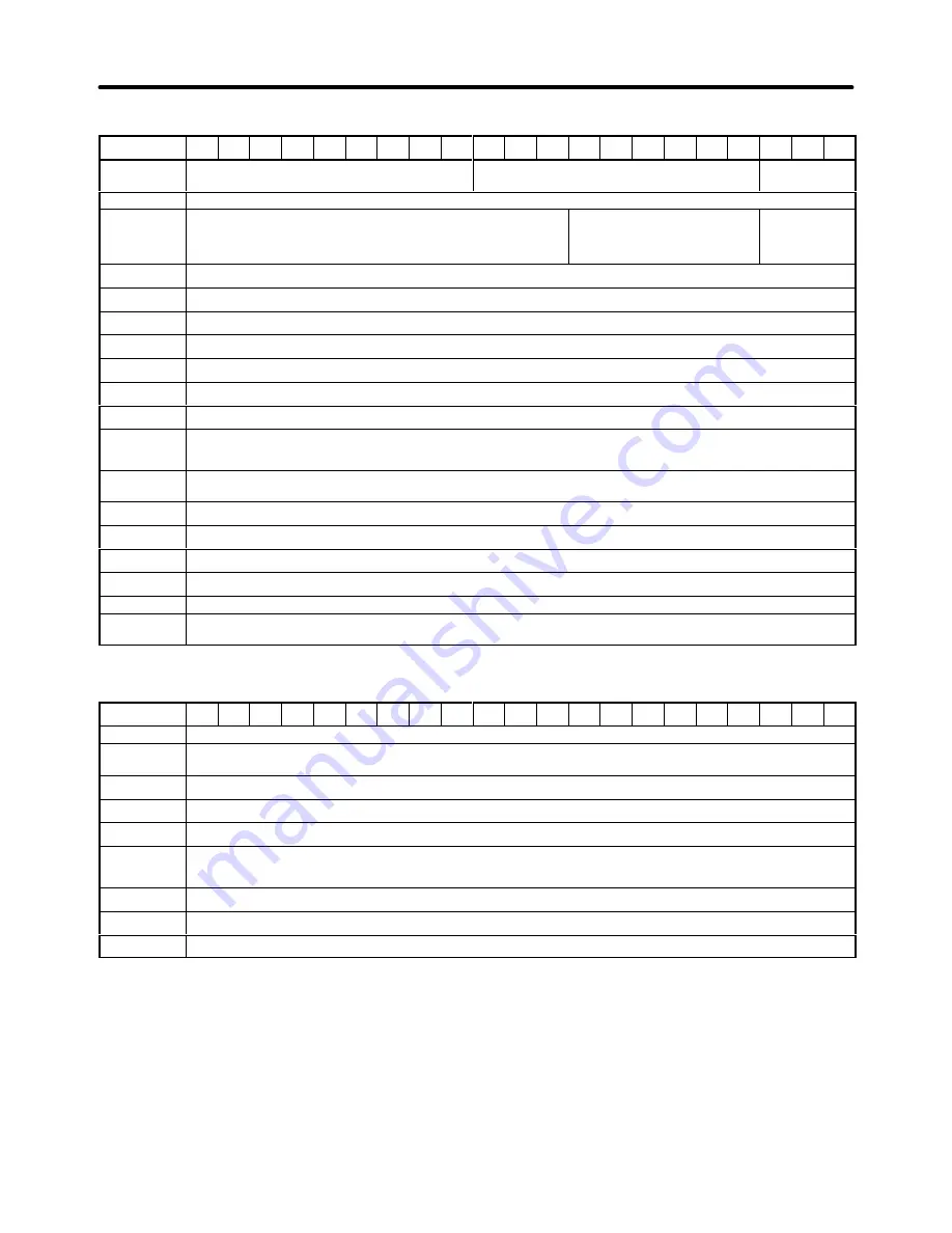
9-5
Control Characteristics
Model number
3G3FV-
A4004
A4007
A4015
A4022
A4037
A4055
A4075
A4110
A4150
B4185
B4220
B4300
B4370
B4450
B4550
B4750
-E
B411K
-E
B416K
-E
B418K
-E
B422K
-E
B430K
-E
Power supply
harmonic coun-
termeasures
DC reactor (option) connection possible.
DC reactor built in
No item
Control method
Sine wave PWM (high-carrier frequency control)
Carrier frequen-
cy
0.4 to 15 kHz (2.0 to 15 kHz in vector control)
0.4 to 10 kHz (2.0 to 10 kHz in
vector control)
0.4 to 2.5 kHz
(2.0 to 2.5 kHz
in vector con-
trol)
Speed control
range
1:100 (1:1000 with PG)
Speed control
precision
±
0.2% (
±
0.02% with PG)
Speed control
response
5 Hz (30 Hz with PG)
Torque charac-
teristics
150% at 1 Hz (150% at 0 rpm with PG). A torque limit function is incorporated.
Torque control
precision
±
5% (with PG)
Torque control
response
40 Hz (with PG)
Frequency con-
trol range
0.1 to 400 Hz
Frequency pre-
cision
(temperature
characteristics)
Digital references:
±
0.01% (–10 to 40
°
C)
Analog references:
±
0.1% (25
±
10
°
C)
Frequency set-
ting resolution
Digital references:
0.01 Hz (Less than 100 Hz), 0.1 Hz (100 Hz or higher)
Analog references:
0.03 Hz/60 Hz (11 bits + sign)
Output frequen-
cy resolution
0.001 Hz
Overload capac-
ity
150% of rated current for one minute
Frequency set-
ting signal
0 to
±
10 VDC (20 k
Ω
), 0 to 10 VDC (20 k
Ω
) voltage input or 4 to 20 mA (250
Ω
) current input
Acceleration/De-
celeration time
0.01 to 6000.0 s (4 selectable combinations of independent acceleration and deceleration settings)
Braking torque
Approximately 20% (Increment possible with an external braking resistor.)
Voltage/frequen-
cy characteris-
tics
Select vector control, one from 15 types of fixed V/f patterns, or set a user V/f pattern.
Protective Functions
Model number
3G3FV-
A4004
A4007
A4015
A4022
A4037
A4055
A4075
A4110
A4150
B4185
B4220
B4300
B4370
B4450
B4550
B4750
-E
B411K
-E
B416K
-E
B418K
-E
B422K
-E
B430K
-E
Motor protection
Protection by electronic thermal.
Instantaneous
overcurrent
protection
Stops at approx. 200% of rated output current.
Overload
protection
Stops in one minute at approx. 150% of rated output current.
Overvoltage
protection
Stops when main-circuit DC voltage is approx. 820 V.
Undervoltage
protection
Stops when main-circuit DC voltage is approx. 380 V.
Momentary pow-
er interruption
compensation
(selection)
Stops for 15 ms or more. By selecting the momentary power interruption mode, operation can be continued if power is
restored within 2 s.
Cooling fin over-
heating
Protection by thermistor.
Grounding
protection
Protection by electronic circuits.
Charge indicator
(internal LED)
Lit when the main circuit DC voltage is approx. 50 V or more.
Specifications
Chapter 9
Содержание SYSDRIVE 3G3FV
Страница 1: ...USER S MANUAL High function General purpose Inverter SYSDRIVE 3G3FV Cat No I516 E1 4 ...
Страница 16: ...Chapter 1 Introduction 1 1 Function 1 2 Nomenclature 1 3 New Functions 1 ...
Страница 33: ...Chapter 2 Installation 2 1 Mounting 2 2 Wiring 2 ...
Страница 112: ...Chapter 4 Trial Operation 4 1 Procedure 4 2 Operation Example 4 ...
Страница 289: ...Chapter 7 Parameter Lists 7 1 Initialize Mode Parameters 7 2 Program Mode Parameter List 7 ...
Страница 366: ...Chapter 9 Specifications 9 1 Inverter Specifications 9 2 Option Specifications 9 ...
Страница 395: ...Chapter 10 Appendix 10 1 Notes on Using the Inverter for a Motor 10 ...