5-12
H
Control Input Interface
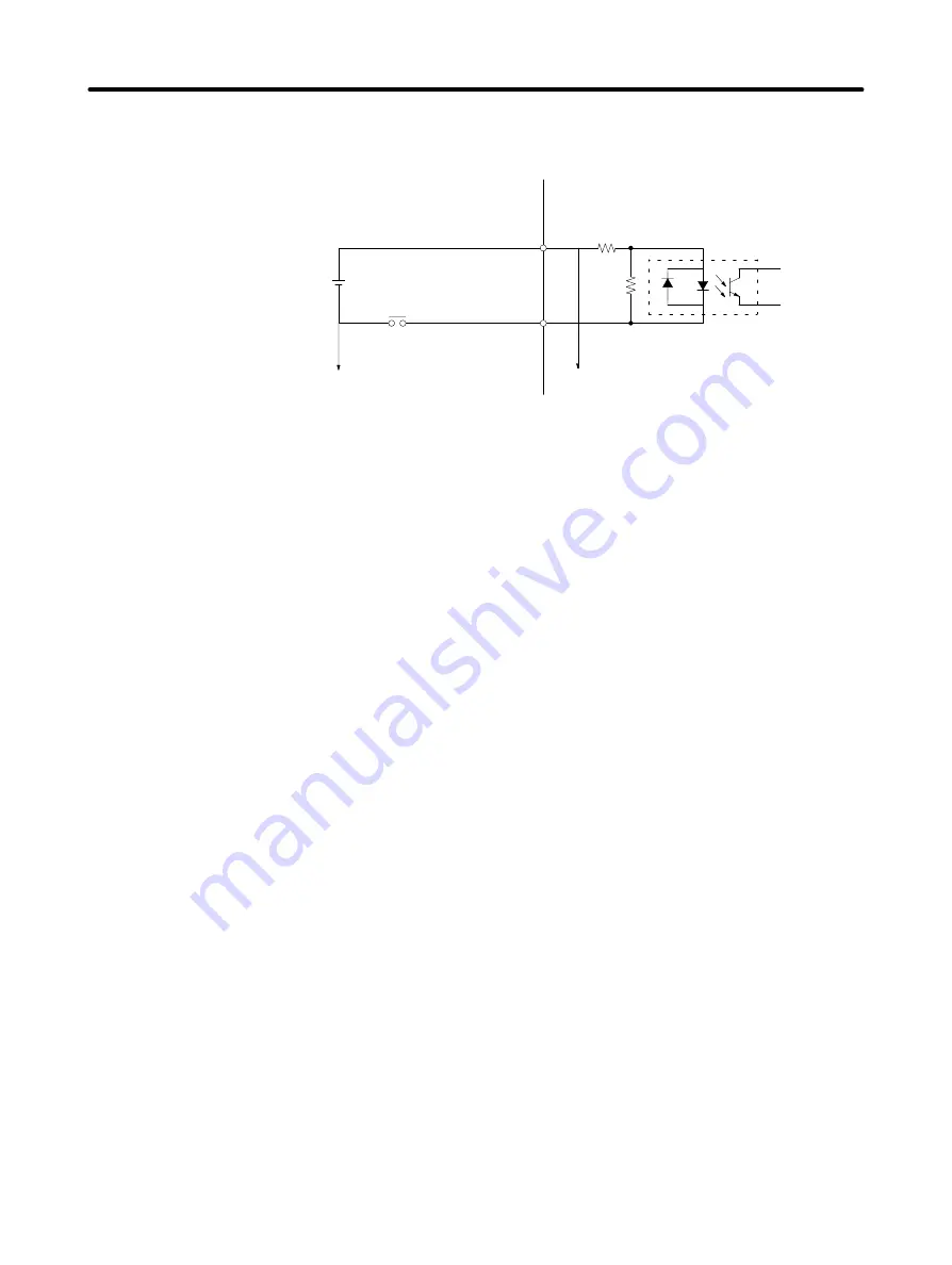
The input circuit for the control I/O connector (CN1) is as shown in the following diagram.
+24 VIN
RUN
13
14
4.7 k
3.3 k
5 mA
External power supply
24-VDC
±
1 V
50 mA min.
To other input circuit GNDs
To other input circuits
D
Run Command (14: RUN)
This is the input that turns on the power drive circuit for the main circuit of the Servo Driver. If this signal is
not input (i.e., servo-off status), the Servomotor cannot operate. Depending on the setting of setup pa-
rameter Cn-01, bit no. 0, this signal can be bypassed. In that case, the servo will be turned on after the
power is turned on.
D
Gain Reduction (15: MING), Pulse Stop (15: IPG),
Rotation Direction Command (15: RDIR)
This input signal can be switched among the following three kinds of signals by changing on the settings
of bit 2 of setup parameter Cn-02 and bit F of setup parameter Cn-01. Select the signal function required
for your application.
•
Gain Reduction (15: MING; Cn-02 Bit No. 2 = 0 and Cn-01 Bit No. F = 0)
Bit F of Cn-01 can be set in HA/LA/V/W Models only. Input this signal to lower the loop gain for the
control loop, and to weaken servo rigidity (repellant force with respect to external force).
When the gain reduction is input, speed loop integration is disabled, decreasing the speed loop gain.
In addition, when parts are inserted after positioning, the insertion operation is made easier because
the repellant force with respect to external force is weakened by the inputting of this signal. This can-
not be used for the vertical shaft where a gravity load is applied, because position deviation will oc-
cur.
•
Pulse Stop (15: IPG; Cn-02 Bit No. 2 = 0 and Cn-01 Bit No. F = 1)
This signal can be used in HA/LA/V/W Models only. Command signals won’t be received internally
while this signal is ON.
•
Rotation Direction Command (15: RDIR; Cn-02, Bit No. 2= 1)
This signal becomes the rotation direction change command for when operation is carried out at the
internally set speed (no. 1 through no. 3 internally set speeds). When this signal is not input, the rota-
tion direction is forward; when it is input, the direction is reverse.
D
Forward Drive Prohibit (16: POT, Cn-01 bit No. 2 = 0)
Reverse Drive Prohibit (17: NOT, Cn-01 bit No. 3 = 0)
These two signals are the inputs for forward and reverse drive prohibit (overtravel). When they are in-
put, driving is possible in the respective directions. When driving is prohibited, movement will stop ac-
Specifications
Chapter 5
Содержание OMNUC 88D-UP20HA
Страница 11: ...Warning Labels for Models Conforming to EC Directives Warning label 1 Warning label 2...
Страница 31: ...2 8 D R88A PR03U 54 57 5 15 6 9 System Design and Installation Chapter 2...
Страница 188: ...5 53 H Mounting Dimensions D R88A TK01U D R88A TK02U Two M5 Three M5 Specifications Chapter 5...


