5-13
cording to the settings of bits nos. 6, 8, and 9 of setup parameter no. 1 (Cn-01). Alarm status will not be
generated at the Driver. When drive prohibition is not used, clear the function by connecting the respec-
tive signal to the external power 24-V GND or setting setup parameter Cn-01, bit nos. 2, 3 = 1,1.
ÍÍÍÍÍÍÍÍÍÍÍÍÍÍÍÍÍÍÍÍÍÍÍÍÍÍÍÍÍÍÍ
ÍÍÍÍÍÍÍÍÍÍÍÍÍÍÍÍÍÍÍÍÍÍÍÍÍÍÍÍÍÍ Í
Í
ÍÍÍÍÍÍÍÍÍÍÍÍÍÍÍÍÍÍÍÍÍÍÍÍÍÍÍÍÍ Í
Í
ÍÍÍÍÍÍÍÍÍÍÍÍÍÍÍÍÍÍÍÍÍÍÍÍÍÍÍÍÍ Í
Í
ÍÍÍÍÍÍÍÍÍÍÍÍÍÍÍÍÍÍÍÍÍÍÍÍÍÍÍÍÍ Í
Í
ÍÍÍÍÍÍÍÍÍÍÍÍÍÍÍÍÍÍÍÍÍÍÍÍÍÍÍÍÍ Í
Í
ÍÍÍÍÍÍÍÍÍÍÍÍÍÍÍÍÍÍÍÍÍÍÍÍÍÍÍÍÍ Í
Í
ÍÍÍÍÍÍÍÍÍÍÍÍÍÍÍÍÍÍÍÍÍÍÍÍÍÍÍÍÍ Í
Í
ÍÍÍÍÍÍÍÍÍÍÍÍÍÍÍÍÍÍÍÍÍÍÍÍÍÍÍÍÍ Í
Í
ÍÍÍÍÍÍÍÍÍÍÍÍÍÍÍÍÍÍÍÍÍÍÍÍÍÍÍÍÍ Í
ÍÍÍÍÍÍÍÍÍÍÍÍÍÍÍÍÍÍÍÍÍÍÍÍÍÍÍÍÍÍÍ
ÍÍÍÍÍÍÍÍÍÍÍÍÍÍÍÍÍÍÍÍÍÍÍÍÍÍÍÍÍÍ
ÍÍÍÍÍÍÍÍÍÍÍÍÍÍÍÍÍÍÍÍÍÍÍÍÍÍÍÍÍ Í
Í
ÍÍÍÍÍÍÍÍÍÍÍÍÍÍÍÍÍÍÍÍÍÍÍÍÍÍÍÍ Í
Í
ÍÍÍÍÍÍÍÍÍÍÍÍÍÍÍÍÍÍÍÍÍÍÍÍÍÍÍÍ Í
Í
ÍÍÍÍÍÍÍÍÍÍÍÍÍÍÍÍÍÍÍÍÍÍÍÍÍÍÍÍ Í
Í
ÍÍÍÍÍÍÍÍÍÍÍÍÍÍÍÍÍÍÍÍÍÍÍÍÍÍÍÍ Í
Í
ÍÍÍÍÍÍÍÍÍÍÍÍÍÍÍÍÍÍÍÍÍÍÍÍÍÍÍÍ Í
Í
ÍÍÍÍÍÍÍÍÍÍÍÍÍÍÍÍÍÍÍÍÍÍÍÍÍÍÍÍ Í
Í
ÍÍÍÍÍÍÍÍÍÍÍÍÍÍÍÍÍÍÍÍÍÍÍÍÍÍÍÍ Í
Í
ÍÍÍÍÍÍÍÍÍÍÍÍÍÍÍÍÍÍÍÍÍÍÍÍÍÍÍÍ Í
ÍÍÍÍÍÍÍÍÍÍÍÍÍÍÍÍÍÍÍÍÍÍÍÍÍÍÍÍÍÍ
Stopping Methods when Forward/Reverse Drive Prohibit is OFF
Bit
No. 8
0
Bit
No. 6
0
1
1
POT (NOT) is OFF
Deceleration Method
Dynamic brake
Free run
Emergency stop torque (Cn-06)
Servo free
Stopped Status
Servo free
Servo locked
Bit
No. 9
0
1
See note
Note The position loop is not valid when stopping with this mode.
D
Forward/Reverse Rotation Current Limit [11, 12: (PCL/SPD1), (NCL/SPD2)]
These input signals switch between the forward/reverse current limit and the speed selection command
signal for the internally set speed, depending on the setting of setup parameter Cn-02 bit no. 2. Set the
required functions for using it.
•
Forward/Reverse Rotation Current Limit (11, 12: PCL, NCL)
When setup parameter Cn-02 bit no. 2 = 0, these input signals become respectively the forward rota-
tion current limit and the reverse rotation current limit, and they limit the current to the Servomotor.
The current limit values can be set for the respective directions by means of user parameters Cn-18
and 19.
•
Speed Selection Command (11, 12: SPD1, SPD2)
When setup parameter Cn-02 bit no. 2 = 1, these input signals become the speed selection com-
mand 1 and the speed selection command 2. Depending on the combination, the Servomotor speed
can be controlled according to the internally set speeds, nos. 1 through 3, which are set in user pa-
rameter Cn-1F, 20, 21. At that time, the CN1-15 pin becomes the rotation direction command (RDIR).
D
Alarm Reset (18: RESET)
This is the external reset signal input for the servo alarm. The alarm is reset when the signal turns ON.
Remove the cause of the alarm and then restart operation. In order to prevent danger, turn OFF the run
command before inputting the reset signal.
D
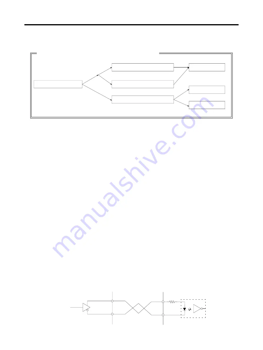
Command Pulse Inputs and Deviation Counter Reset Inputs
The input circuits for command pulse and deviation counter reset inputs are shown in the following dia-
gram.
Line-driver Input
Controller side
Servo Driver side
Applicable line driver
AM26LS31A or equivalent
220
Ω
+
–
+
–
Specifications
Chapter 5
Содержание OMNUC 88D-UP20HA
Страница 11: ...Warning Labels for Models Conforming to EC Directives Warning label 1 Warning label 2...
Страница 31: ...2 8 D R88A PR03U 54 57 5 15 6 9 System Design and Installation Chapter 2...
Страница 188: ...5 53 H Mounting Dimensions D R88A TK01U D R88A TK02U Two M5 Three M5 Specifications Chapter 5...


