CHAPTER 3 REPAIR PROCEDURES
3.2.4. Load Cell Assembly
4. Once the Ratio Beam is centered, remove the Brass Rod in the front and the
Threaded Rod in the back, and gently move the Ratio Beam up and down from the
rear, checking for any friction. If there is friction, replace the Brass Rod and repeat
the centering process.
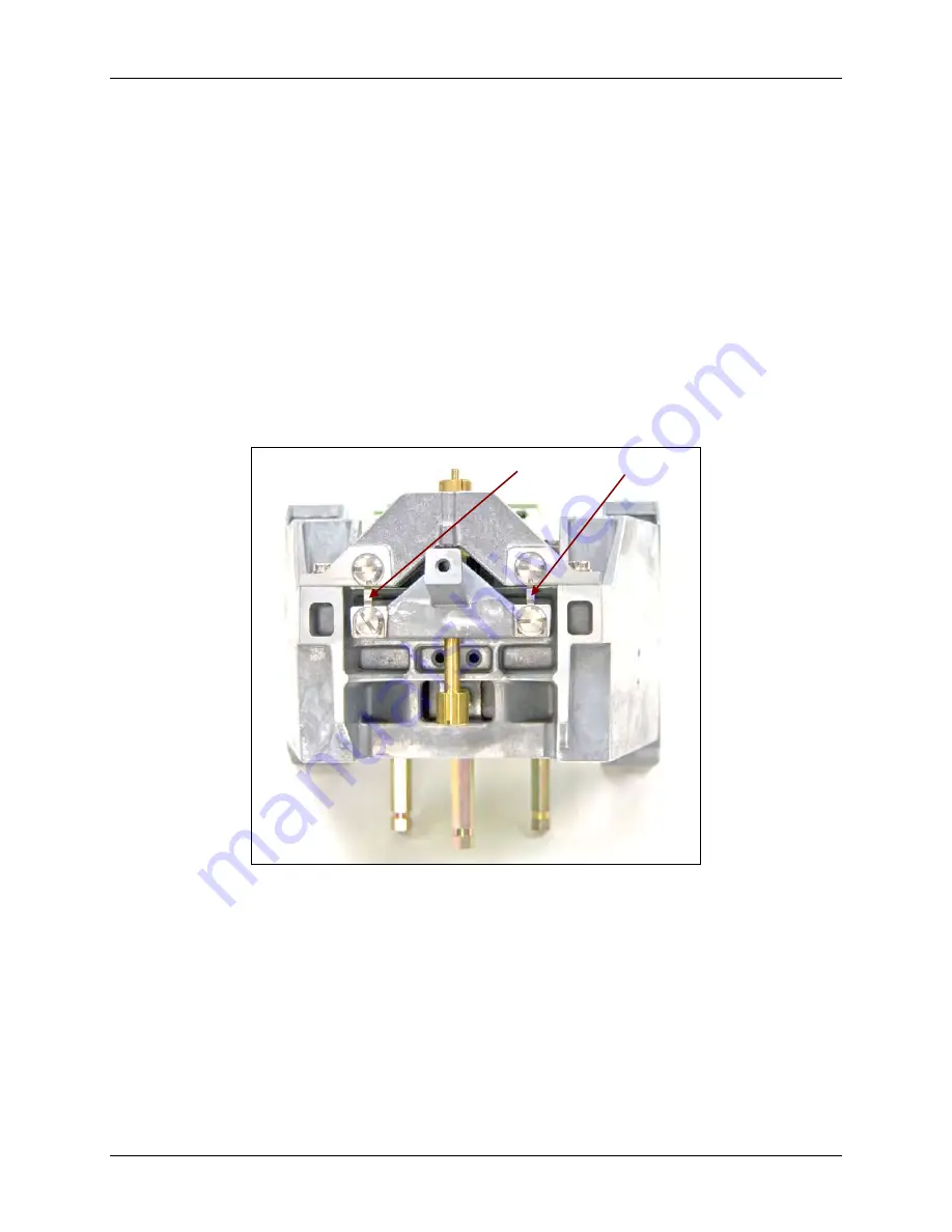
5. Tighten the screws on each side of the yoke (shown in Figure 3-65) when the Ratio
Beam is centered. Re-check movement.
NOTE:
If Ratio Beam Coil does not center properly over the Magnet and
Temperature Sensor Tube, the
Ratio Beam Flexures
must be checked to see if they
are bent. Place each Flexure on a clean flat surface and check that both sides rest
evenly on the surface. If they don’t, replace them.
3.2.5.1 Ratio Beam Flexure Replacement
5.1 Ensure yoke is aligned evenly side-to-side with frame, and flush with frame
on front.
Ratio Beam Flexures
Figure 3-65. Yoke aligned with frame side-to-side,
and flush with frame on front.
5.2. Re-install Hanger with Brass Fixture and Thumb screws.
5.3. Insert Brass Brackets on both sides. (See Figure 3-66, next page.)
5.4. Press Brackets from each side, and Brass Fixture from below, to ensure that
Brackets are snug against yoke, so that if Brackets are pulled there is
resistance.
Ohaus Corporation www.ohaus.com
3-32
Discovery Balance Service Manual
Содержание DISCOVERY BALANCE
Страница 2: ......
Страница 4: ......
Страница 10: ...TABLE OF CONTENTS Ohaus Corporation www ohaus com vi Discovery Balance Service Manual...
Страница 99: ...80104135 P N 80104135 SERVICE MANUAL DISCOVERY BALANCE...


