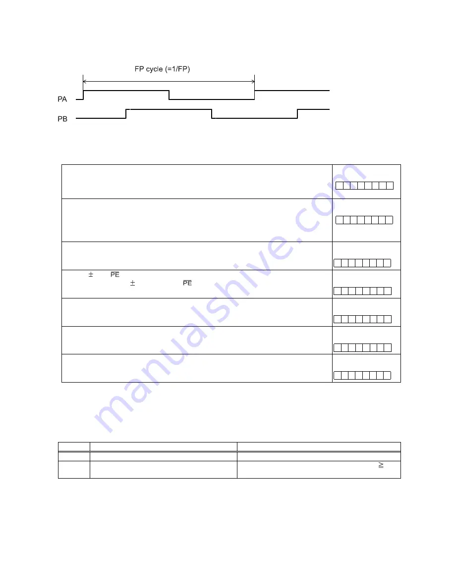
-
50
-
FP
<
(speed)
/
(input
I/F
multiply
value)
Example:
When
the
pulse
input
setting
speed
is
1000
pps
with
a
90
˚ phase difference and a 2x input
multiplication
rate,
the
input
frequency
on
the
PA
terminal
is
less
than
500
Hz.
Note:
When
the
PA/
PB
input
frequency
fluctuates,
take
the
shortest
frequency,
not
average
frequency,
as
"Frequency
of
FP"
above.
<Setting
relationship
of
PA/PB
input>
Specify
the
PA/PB
input
<Set
to
PIM0
to
1
(bit
20
to
21)
in
RENV2>
00:
90
˚ phase difference, 1x 10: 90˚ phase difference, 4x
01:
90
˚ phase difference, 2x 11: 2 sets of up or down input pulses
[RENV2]
(WRITE)
23
16
-
-
n
n
-
-
-
-
Specify
the
PA/PB
input
count
direction
<Set
to
PDIR
(bit
23)
in
RENV2>
0:
Count
up
when
the
PA
phase
is
leading.
Or,
count
up
on
the
rising
edge
of
PA.
1:
Count
up
when
the
PB
phase
is
leading.
Or,
count
up
on
the
rising
edge
of
PB.
[RENV2]
(WRITE)
23
16
n
-
-
-
-
-
-
-
Enable/disable
PA/PB
input
<Set
POFF
(bit
15)
in
RENV2>
0:
Enable
PA/PB
input
1:
Disable
PA/PB
input.
[RENV2]
(WRITE)
15
8
n
-
-
-
-
-
-
-
Set
the
DR,
input
filter
<Set
DRF
(bit
27)
in
RENV1>
1:
Insert
a
filter
on
DR
input
and
input
By
setting
the
filter,
the
PCL
ignores
signals
shorter
than
32
msec.
[RENV1]
(WRITE)
31
24
-
-
-
-
n
-
-
-
Reading
operation
status
<CND
(bit
0
to
3)
in
RSTS>
1000
:
wait
for
PA/
PB
input.
[RSTS]
(READ)
7
0
-
-
-
-
n
n
n
n
Reading
PA/PB
input
error
<ESPE
(bit
8)
in
REST>
ESPE
(bit
17)
=
1:
Occurs
a
PA/PB
input
error
[REST]
(READ)
15
8
0
0
0
0
0
0
0
n
Reading
PA/PB
input
buffer
counter
status
<ESP0
(bit
6)
in
REST>
ESPO
(bit
6)
=
1:
Occurs
an
overflow.
[REST]
(READ)
7
0
-
n
-
-
-
-
-
-
*
In
the
descriptions
in
the
right
hand
column,
"n"
refers
to
the
bit
position.
"0"
refers
to
bit
positions
where
it
is
prohibited
to
write
any
value
except
zero
and
the
bit
will
always
be
zero
when
read.
The
pulsar
input
mode
has
the
following
2
operation
types.
The
direction
of
movement
for
continuous
operation
can
be
changed
by
setting
the
RENV2
register,
without
changing
the
wiring
connections
for
the
PA/PB
inputs.
MOD
Operation
mode
Direction
of
movement
01h
Continuous
operation
using
pulsar
input
Determined
by
the
PA/PB
input.
51h
Positioning
operation
using
pulsar
input
(absolute
position)
Feeds
in
a
positive
direction
when
PRMV
0.
Feeds
in
a
negative
direction
when
PRMV
<
0.
Содержание PCL6113
Страница 1: ...User s Manual For PCL6113 6123 6143 Pulse Control LSI Nippon Pulse Motor Co Ltd...
Страница 11: ...5 3 Terminal Assignment Diagram 3 1 PCL6113 3 2 PCL6123...
Страница 20: ...14 5 Block Diagram...
Страница 115: ...109 11 Stop timing by error...
Страница 116: ...110 13 External Dimensions 13 1 PCL6113...
Страница 117: ...111 13 2 PCL6123...
Страница 118: ...112 13 3 PCL6143...


