Chapter 17 – Connecting the telephones and attendant console
Page 163 of 536
Option 11C Compact
Planning, Installation, Fault Clearing and CCBR Guide
Connecting off-premise telephones
Off-premise 500/2500-type telephones must be connected through an
NTAK92AA Off-Premise Protection module. Each module can connect up to
four analog telephones and can interface with an NTMW06 Analog Line Card
or with an NTMW07 Trunk/Line Card.
Procedure 22
Connecting an off-premise telephone.
1
Mount the NTAK92AA Off-Premise protection module on the wall
using four #10 1/2 in (minimum) screws.
2
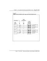
Connect a #6 AWG ground wire from the ground lug at the bottom
of the NTAK92AA Off-Premise protection module to an earth
ground. Refer to
.
3
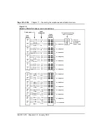
Connect two NTAK9204 cables (one from connector J1 and one
from connector J2) from the protection module to the
cross-connect terminal.
Terminate the cables as shown in
.
WARNING
The message waiting indicator produces -150 volts which is
considered hazardous on off-premise telephones. Make sure that the
-150 V is disabled on off-premise telephones. The voltage is disabled
when the Class Of Service (CLS) assigned to the telephone is LPD
(message waiting lamp denied) and MWD (Message Waiting Denied)
in LD 10. Refer to the Software Guide for information about LD 10.
Under no circumstances should LPA or MWA be assigned in the Class
of Service on off-premise telephones
WARNING
If connecting to a message waiting line card, unseat the card from its
assigned slot before proceeding with the next step.
Содержание Meridian Meridian 1
Страница 3: ...553 3121 210 Standard 3 0 January 1999 ...
Страница 17: ...xiv Contents 553 3121 210 Standard 3 0 January 1999 ...
Страница 89: ...Page 70 of 536 Chapter 6 Bracing cabinets against earthquakes 553 3121 210 Standard 3 0 January 1999 ...
Страница 97: ...Page 78 of 536 Chapter 8 Installing a new system 553 3121 210 Standard 3 0 January 1999 ...
Страница 107: ...Page 88 of 536 Chapter 10 Installing the system ground 553 3121 210 Standard 3 0 January 1999 ...
Страница 113: ...Page 94 of 536 Chapter 11 Installing the power supply 553 3121 210 Standard 3 0 January 1999 ...
Страница 125: ...Page 106 of 536 Chapter 12 Adding an expansion cabinet 553 3121 210 Standard 3 0 January 1999 ...
Страница 139: ...Page 120 of 536 Chapter 13 Installing the circuit cards 553 3121 210 Standard 3 0 January 1999 ...
Страница 157: ...Page 138 of 536 Chapter 15 Installing and connecting SDI and Ethernet ports 553 3121 210 Standard 3 0 January 1999 ...
Страница 175: ...Page 156 of 536 Chapter 16 Starting up and testing the system 553 3121 210 Standard 3 0 January 1999 ...
Страница 209: ...Page 190 of 536 Chapter 18 Connecting the trunks 553 3121 210 Standard 3 0 January 1999 ...
Страница 323: ...Page 304 of 536 Chapter 21 Installing Hospitality 553 3121 210 Standard 3 0 January 1999 ...
Страница 419: ...Page 400 of 536 Chapter 23 Pre programmed data 553 3121 210 Standard 3 0 January 1999 ...
Страница 455: ...Page 436 of 536 Chapter 24 Changing pre programmed data 553 3121 210 Standard 3 0 January 1999 ...
Страница 555: ...Page 536 of 536 Chapter 25 Fault locating and clearing 553 3121 210 Standard 3 0 January 1999 ...


